
Fire, heat and high voltage cable protection wrap

a protection wrap and high-voltage cable technology, applied in the field of wrap systems, can solve the problems of lenient acceptance criteria, scale test does not adequately model real-world conditions, 5343 fails to measure and limit parameters critical to the protection of installed cables

Inactive Publication Date: 2009-03-26
NO FINE TECH INC +1
View PDF16 Cites 39 Cited by
  • Summary
  • Abstract
  • Description
  • Claims
  • Application Information

AI Technical Summary

Benefits of technology

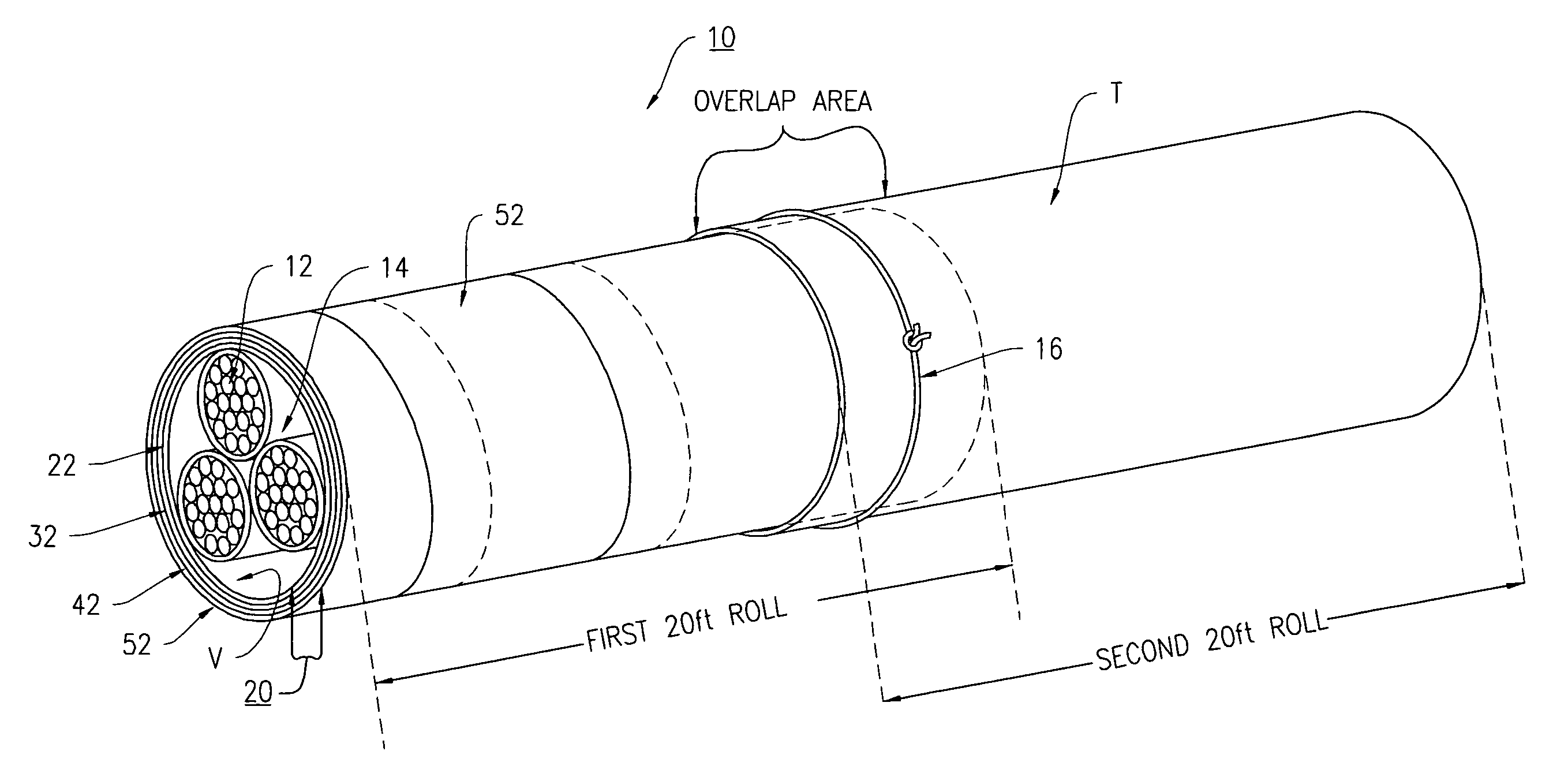
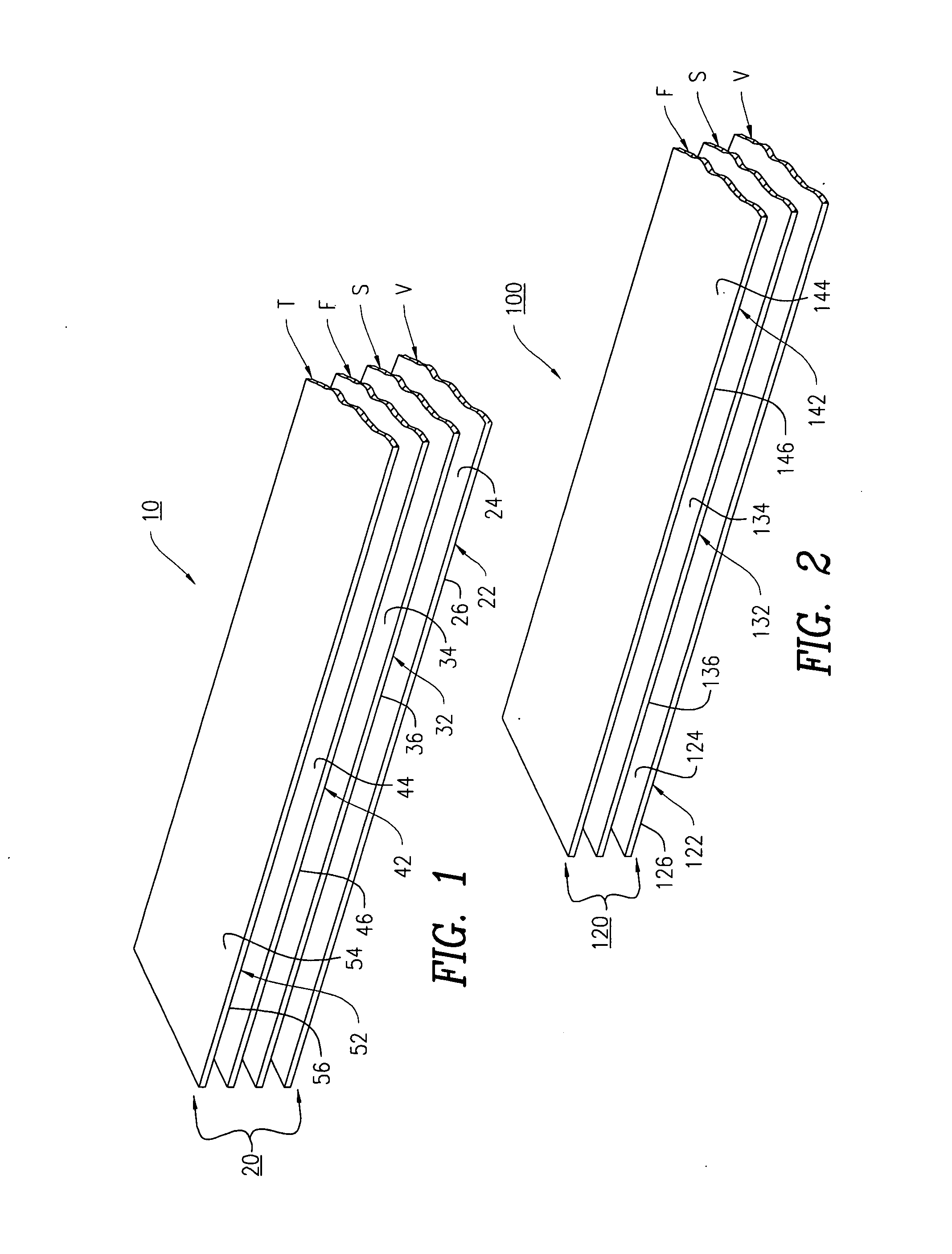
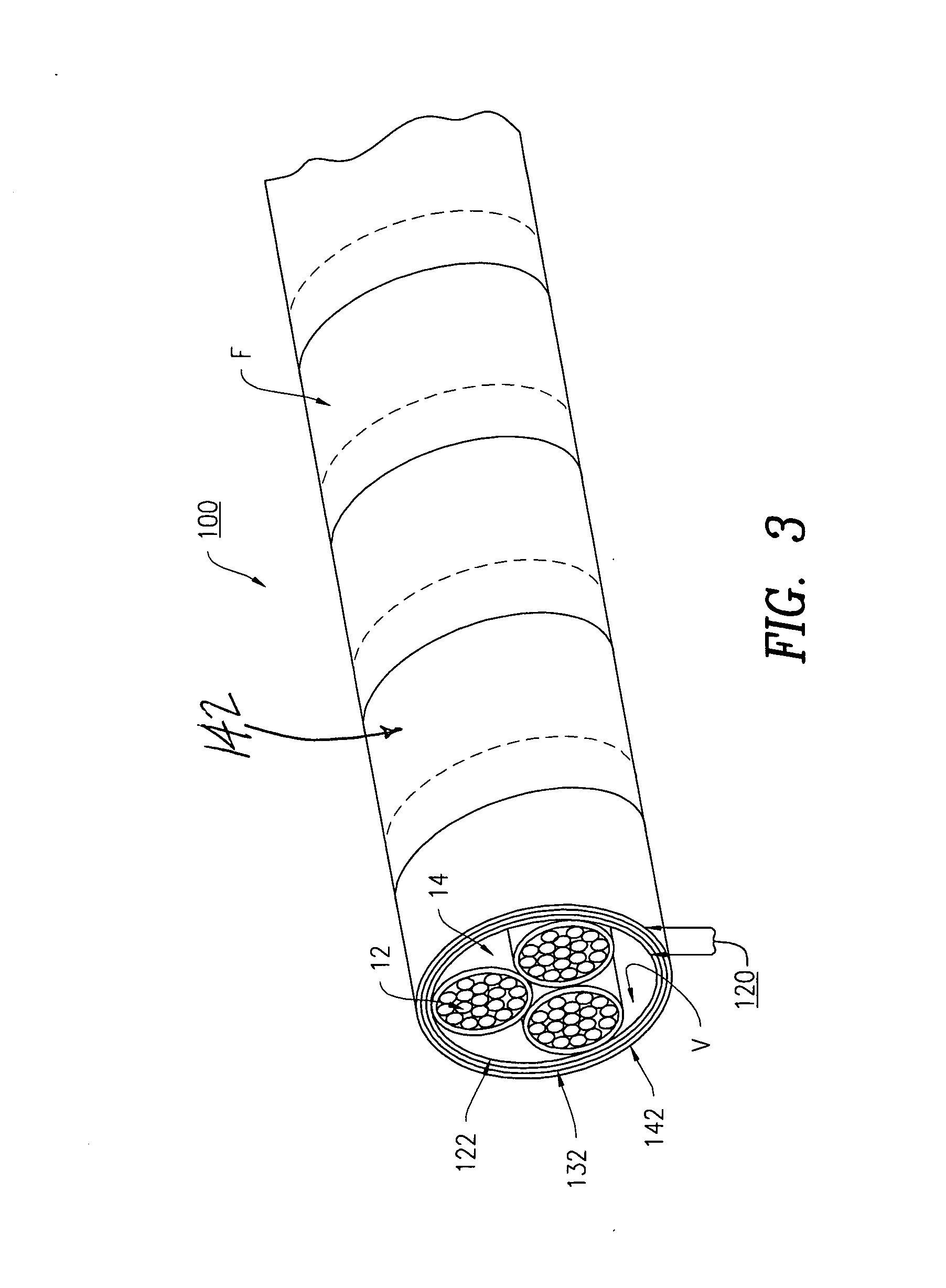
[0055]In accordance with the present invention, there is provided a fire, heat and high voltage cable wrap system for protecting wires and cables. The protective cable wrap system includes a support layer for strength being selected from the group consisting of woven, non-woven, knitted, netted or matted materials; a high voltage arc resistant layer for protection against high voltage; a fire protective coating layer for protecting the cable wrap system against

Problems solved by technology

This small-scale test does not adequately model real world conditions and allows very lenient acceptance criteria.
Further, the Con Ed EO-5343 fails to measure and limit parameters critical to the protection of installed cables, including; flame spread, ignition, Rate of Heat Release (RHR), smoke development and toxic products of combustion.
Electric Utility problems associated with cable flame spread, ignition, fire damage, smoke, toxicity and widespread power outages continue today.
Modest improvements to inadequate current products provide little additional benefit to severe problems.
The approval testing for these products for use in current electrical systems were based on very low levels of performance such as the small-scale Bunsen burner tests described above.
While these products can surpass these sample tests, they do not nearly provide the high level of fire protection necessary for multiple cables in real world conditions.
In addition, these thermoplastics, even with their additives, ignite at relatively low temperatures, have very high rates of combustion, and emit highly toxic products of combustion, many times the lethal levels.
These types of protection systems are designed mainly for cable trays or boxes, they are labor intensive to install, very heavy, very expensive and do not provide the necessary fire protection.
There is no protection against flame spread or heat protection.
Additionally, these products emit high levels of toxic products combustion as measured by NES 713.
As mentioned previously, these tests do not model the severe fire exposure of cables in real world situations.
When tested according to IEC 332 / 3, the cables burned for 1.3 m. While this is technically a passing grade (2 m is failure) it does not provide the fire protection necessary for severe, real world exposures.
Further, there is no protection to heat penetration to the cable core.
The intumescent coating on a support layer does not provide the cable protection required, including insufficient heat penetration protection, water and chemical resistance, abrasion protection of high voltage and arc protection.
Additionally, the use of material such as fiberglass is prohibited by electric companies due to the potential hazard to installers.
In the Keogh '412 alternate embodiment, with addition of a layer such as mica, there is additional rigidity, cost and toxic by products of combustion.
Further, there is no high voltage and arc protection.
None of the aforementioned prior art references disclose a fire, heat, high voltage and environmental protection cable wrap system that eliminates or substantially reduces fire and flame spread along the length of a cable or cable bundle.

Method used


Image

  • Fire, heat and high voltage cable protection wrap
  • Fire, heat and high voltage cable protection wrap
  • Fire, heat and high voltage cable protection wrap

Examples


example 1

[0065]The cable wrap system 10 as disclosed in claim 1 is constructed as follows:

[0066]1) High voltage arc resistant layer 22 is comprised of W.R. Grace Quelpyre Resin, approximately 0.040″ coating thickness.

[0067]2) Woven structural layer 32 is polyester having a thickness of 0.010″

[0068]3) Fire protection layer 42 is NoFire A18, manufactured by NoFire Technologies.

[0069]4) Topcoat environmental layer 52 is an elastomeric, acrylic coating.

[0070]The cable wrap system 10 is used to wrap a three-cable bundle 14 of high voltage cables 12 similar to the ones used by the Distribution Section of Consolidated Edison of New York (Con Ed) (See FIG. 4). The wrapped bundle is installed in a vertical burn apparatus similar to the type used to conduct ANSI / IEEE 383 Fire Tests. Test setup, test conditions, exposure, time and acceptance criteria are specified by the Standard.

[0071]Results of ANSI / IEEE 383 Fire Test:

[0072]1) No cable ignition or fire involvement for duration of the test (10 minutes...

example 2

[0076]The cable wrap system 10 of Example #1 is tested according to ASTM E162 for flame spread, smoke generation and ignition potential. The results of this test are: FSI—0, SDI—10, no ignition.

example # 3

Example #3

[0077]The cable wrap of Example #1 is tested according to ASTM E662 for smoke emission and toxic products of combustion using the Drager Tube Method, according to BSS 7239 Gas Analysis.

Results of smoke emission are:FlamingNon-FlamingDs @ 90 sec01Ds @ 4 min103.5Dm2424

Results of Gas Analysis (in parts per million):Gas (type):Non FlamingFlamingHydrochloric Acid (HCL)00Hydro cyanic Acid (HCN)00Hydrogen Fluoride (HF)00Nitrous Fumes (NO + NO2)2.55Carbon Monoxide (CO)7.527.5Sulfur Dioxide (SO2)00Phosgene (CL2CO)00


PUM

PropertyMeasurementUnit
Temperatureaaaaaaaaaa

Abstract

A fire, heat and high voltage cable wrap system for protecting wires and cables. The protective cable wrap system includes a support layer for strength being selected from the group consisting of woven, non-woven, knitted, netted or matted materials; a high voltage arc resistant layer for protection against high voltage; a fire protective coating layer for protecting the cable wrap system against fire; and a top coating layer for resistance to water, chemicals, gases, environmental factors and mechanical damage. The support layer, the high voltage arc resistant layer, the fire protective coating layer and the top coating layer are laminated together for forming a composite laminate structure having a plurality of concentric layers for the protection of transmission wires, electrical wires and cables that provides for high voltage isolation up to 50 kV.

Description

FIELD OF THE INVENTION[0001]The present invention relates to a wrap system that provides fire, heat and high voltage protection for cables, especially power distribution cables. It reduces or eliminates fire spread and the emission of smoke and toxic products of combustion. It prevents or reduces spread of cable failure to adjacent cables in the event of a single cable failure due to a fire, insulation breakdown due to heat or arcing, environmental factors or catastrophic cable failure.BACKGROUND OF THE INVENTION[0002]The grid of electric power distribution in the United States includes main, secondary and tertiary high voltage (high tension) cables installed underground in conduits and ducts, normally accessible by manholes. In a large Metropolitan area, such as New York City, servicing millions of customers, there are numerous cables installed in cable bundles in a particular duct or conduit. Under normal operation, the cable jacket and insulation provides adequate thermal and ele...

Claims


Application Information

Patent Timeline
IPC IPC(8): B32B7/02B32B17/10B32B27/38B32B9/04B32B27/40
CPCH01B3/443H01B3/46Y10T428/26Y10T428/263H01B7/29Y10T428/31504Y10T428/31515Y10T428/31551
Inventor GOTTFRIED, SAMUELHARDING, PETER
Owner NO FINE TECH INC
Learn More