

Method for luminescent layer formation and organic electroluminescent device
- Summary
- Abstract
- Description
- Claims
- Application Information
AI Technical Summary
Benefits of technology
Problems solved by technology
Method used
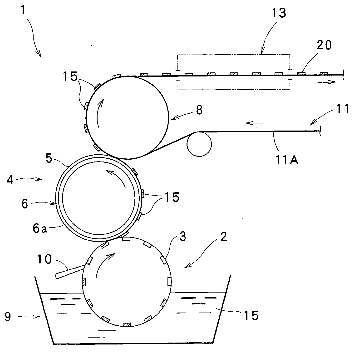
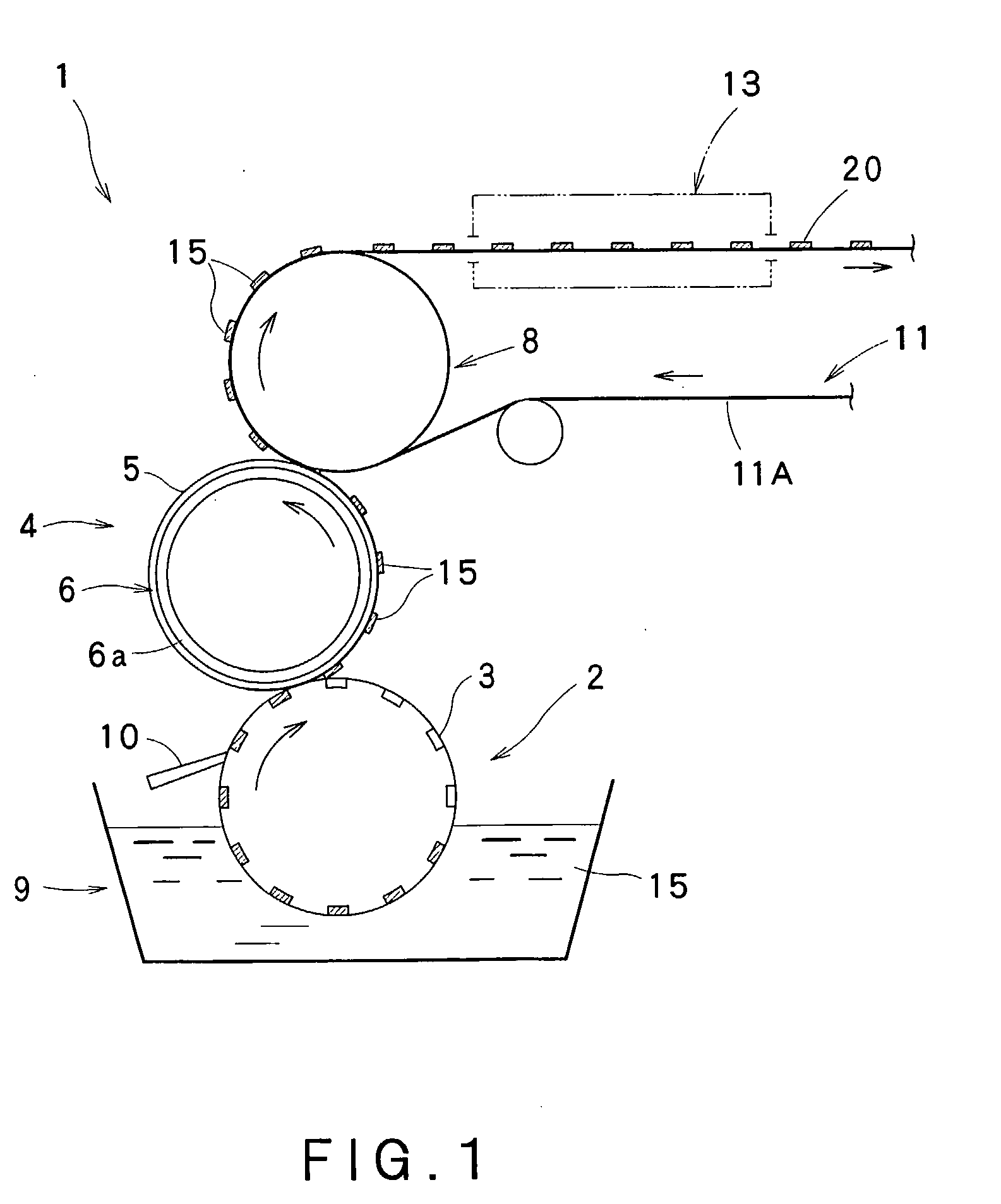
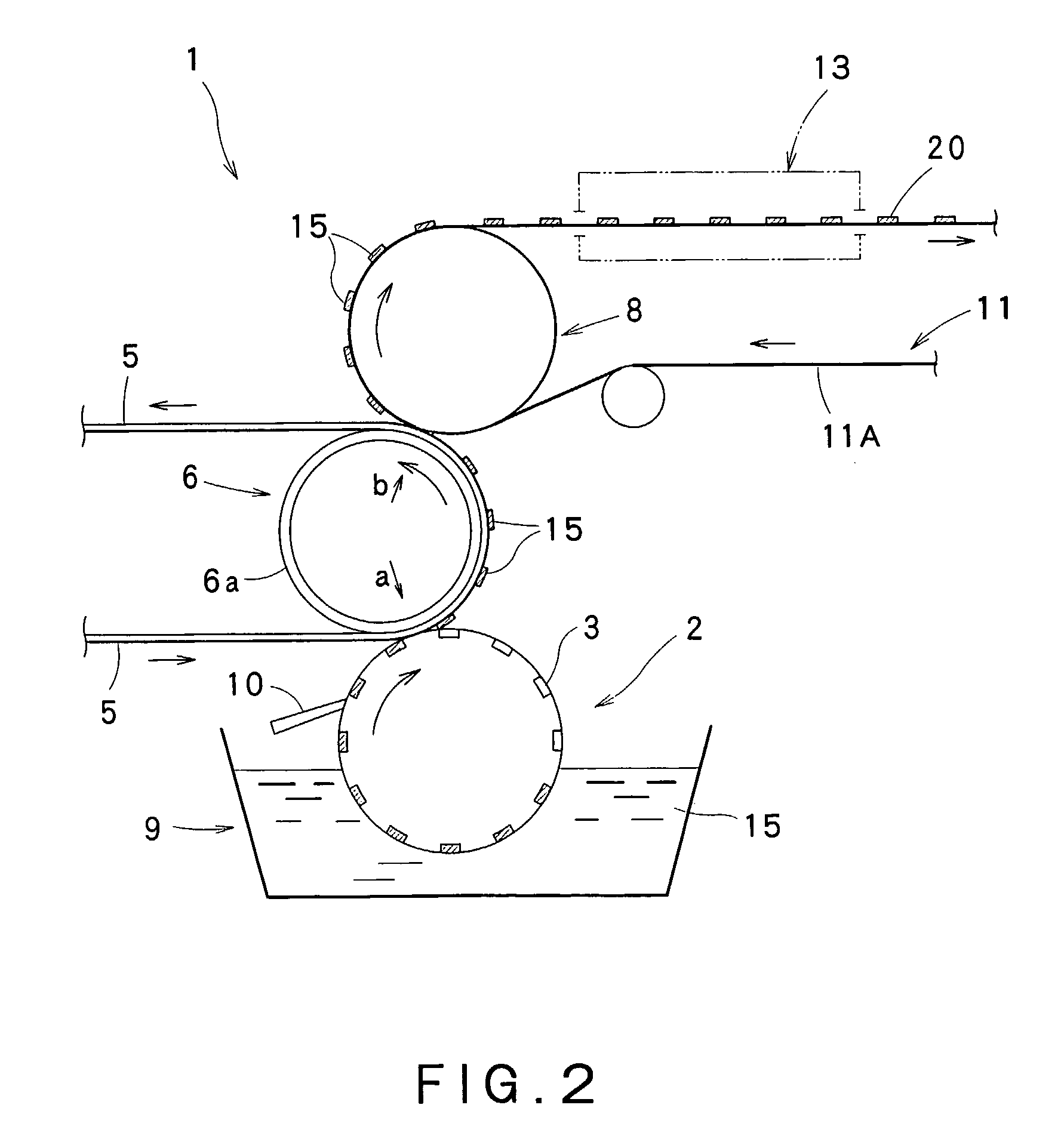
Image

Examples
example 1
[0131]An ink A1 for a red luminescent layer according to the following formulation was prepared. The viscosity of this ink A1 was measured with a viscoelastometer (model MCR 301, manufactured by Physica) in a steady flow measurement mode under conditions of shear rate 100 / sec and ink temperature 23° C. and was found to be 80 cP. The surface tension of mesitylene and tetralin used as solvents was measured at a liquid temperature of 20° C. with a surface tension balance (model CBVP-Z, manufactured by Kyowa Interface Science Co., Ltd.).
Composition of Ink A1 for Red Luminescent Layer
[0132]Polyfluorene derivative-type red luminescent material (molecular weight: 300,000) 2.5% by weight[0133]Solvent (mixed solvent of mesitylene:tetralin=50:50) 97.5% by weight
(Surface tension of mixed solvent=32 dynes / cm, boiling point=186° C.)
(Surface tension of mesitylene=28 dynes / cm, boiling point=165° C.)
(Surface tension of tetralin=35.5 dynes / cm, boiling point=207° C.)
[0134]Further, a plate-shaped grav...
example 2
[0146]Eight types of inks for a red luminescent layer (A1 to A8) were prepared using mixed solvents having boiling points as shown in Table 2 below, based on the ink A1 for a red luminescent layer used in Example 1. The surface tension of the mixed solvents was not more than 40 dynes / cm, and the viscosity of the inks as measured under conditions of ink temperature 23° C. and shear rate 100 / sec was in the range of 5 to 200 cP.
[0147]On the other hand, the same gravure form as used in Example 1 was provided in this Example.
[0148]Resin film F3 (T60 manufactured by Toray Industries, Inc., thickness 75 μm, surface tension 38 dynes / cm) as described in Example 1 was mounted on the circumferential surface of the blanket cylinder as described in Example 1 to prepare a blanket.
[0149]Next, the above gravure form and blanket were mounted on a flat offset printing machine, and a red luminescent layer (thickness about 70 nm) was formed on a glass substrate using each of the inks for a red luminesc...
example 3
[0152]Eight types of inks for a red luminescent layer (A′1 to A′8) were prepared using mixed solvents having surface tensions as shown in Table 3 below, based on the ink A1 for a red luminescent layer used in Example 1. The boiling point of the mixed solvents was in the range of 150 to 250° C., and the viscosity of the inks as measured under conditions of ink temperature 23° C. and shear rate 100 / sec was in the range of 5 to 200 cP.
[0153]On the other hand, the same gravure form as used in Example 1 was provided in this Example.
[0154]Resin film F3 (T60 manufactured by Toray Industries, Inc., thickness 75 μm, surface tension 38 dynes / cm) as described in Example 1 was mounted on the circumferential surface of the blanket cylinder as described in Example 1 to prepare a blanket.
[0155]Next, the above gravure form and blanket were mounted on a flat offset printing machine, and a red luminescent layer (thickness about 70 nm) was formed on a glass substrate using each of the inks for a red l...
PUM
| Property | Measurement | Unit |
|---|---|---|
| Temperature | aaaaa | aaaaa |
| Temperature | aaaaa | aaaaa |
| Fraction | aaaaa | aaaaa |
Abstract
Description
Claims
Application Information