Calculation method, generation method, program, exposure method, and mask fabrication method

a mask fabrication and calculation method technology, applied in the field of calculation methods, can solve the problems of requiring a long time and high cost, requiring socs to calculate the tcc (transmission cross coefficient) and decompose it into eigenvalues, and achieve the effect of short period of time and short period of tim

Active Publication Date: 2009-04-09
CANON KK
View PDF8 Cites 20 Cited by
  • Summary
  • Abstract
  • Description
  • Claims
  • Application Information

AI Technical Summary

Benefits of technology

[0010]The present invention provides a calculation method which can calculate the TCC in an exposure apparatus in a short period of time. The present invention provides a calculation method which can calculate a light intensity distribution, which is formed on the image plane of a projection optical system, in a short period of time. The present invention provides a generation method which can generate data of a pattern of a mask in a short period of time.

Problems solved by technology

At present, however, as the degree of difficulty of exposure is increasing, the detection of the exposure conditions based on experiments requires a long time and high cost.
Unfortunately, the SOCS requires much time to calculate the TCC (Transmission Cross Coefficient) and decompose it into eigenvalues and eigenfunctions.

Method used


Image

  • Calculation method, generation method, program, exposure method, and mask fabrication method
  • Calculation method, generation method, program, exposure method, and mask fabrication method
  • Calculation method, generation method, program, exposure method, and mask fabrication method

Examples


first embodiment

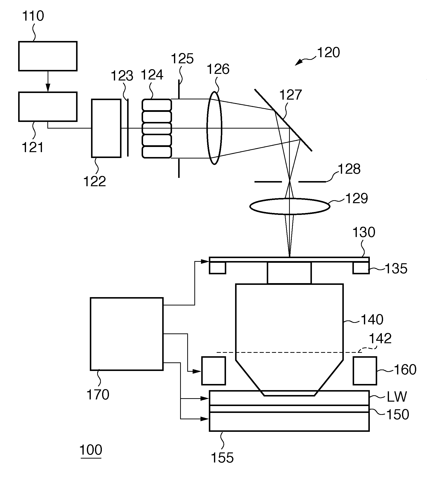
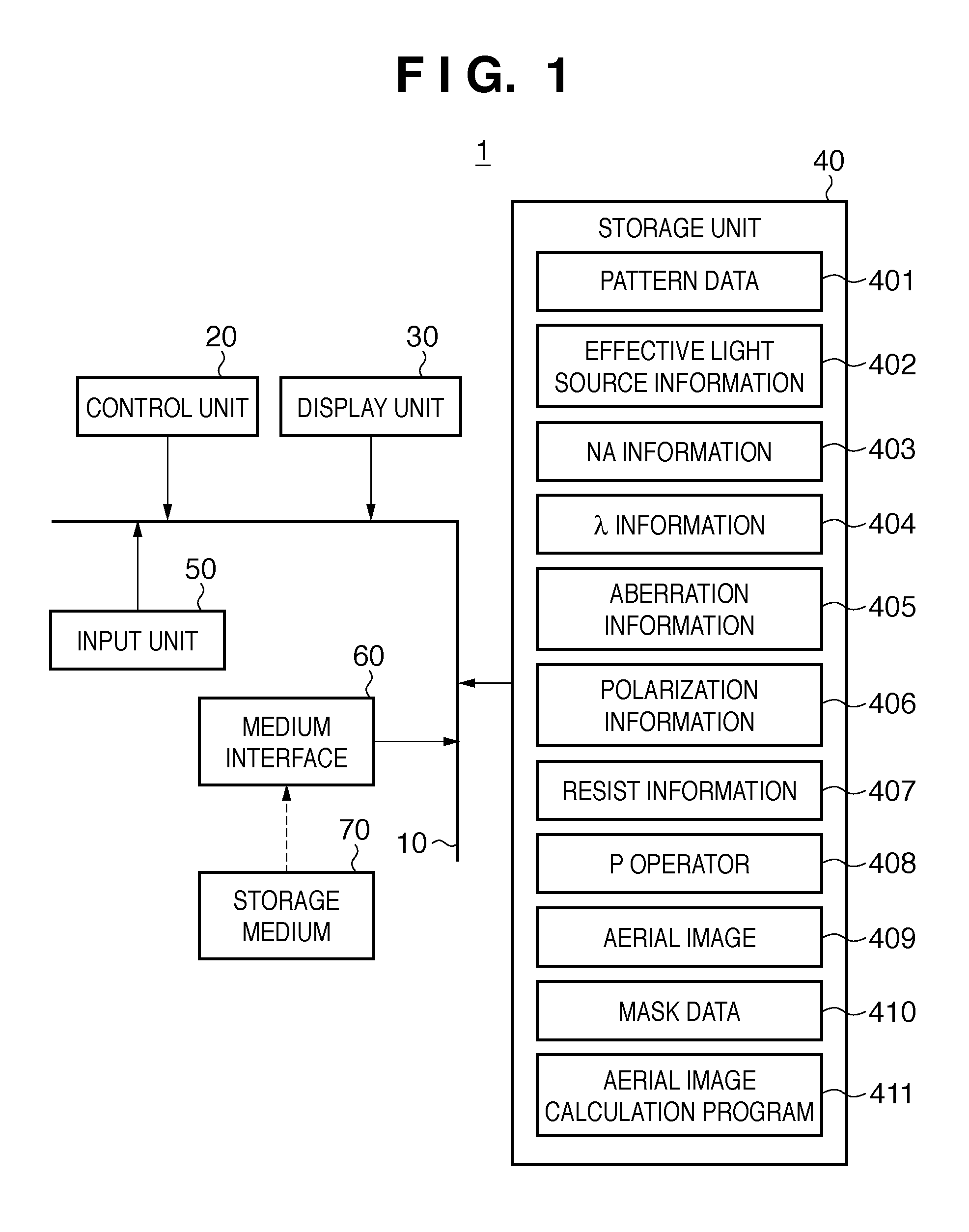
[0130]The effect of a process of calculating an aerial image 409 by an aerial image calculation program 411 will be explained in the first embodiment. In the first embodiment, 64-bit Opteron® is used as a CPU which constitutes a control unit 20 of a processing apparatus 1, and a memory of about 10 gigabytes is used as a storage unit 40. The aerial image calculation program 411 is generated using MATLAB®, and the time taken to calculate the aerial image 409 (calculation time) is compared with that in the prior art (SOCS).

[0131]The first embodiment assumes a case in which an exposure apparatus uses a projection optical system having an NA of 0.73 (corresponding to NA information 403), and exposure light having a wavelength of 248 nm (corresponding to λ information 404). In addition, the projection optical system is assumed to have no aberration (corresponding to aberration information 405), the illumination light is assumed to be non-polarized (corresponding to polarization informatio...

second embodiment

[0136]A process of calculating an aerial image 409 when the aberration of the projection optical system is taken into consideration or when the illumination light is polarized will be explained in the second embodiment. A process of calculating an aerial image 409 when the effective light source has a variation in light intensity (the light intensity of the light-emitting part is nonuniform) or when the diffraction efficiency of light diffracted by the mask pattern changes will also be explained in the second embodiment.

[0137]When the aberration of the projection optical system is taken into consideration, it is only necessary to include the aberration in the pupil function and calculate a P operator 408 using equation (27). In this case, each element of the P operator 408 includes a conjugate element corresponding to the aberration of the projection optical system. The aberration of the projection optical system can be included in P′i in equation (27) in this way.

[0138]Pieces of ae...

third embodiment

[0147]The third embodiment will exemplify a case in which a process of calculating an aerial image 409 by an aerial image calculation program 411 is applied to the model-based RET. The OPC (Optical Proximity Correction) is known as a basic approach to the RET.

[0148]Pieces of aerial image calculation information other than mask data 410 are assumed to be the same as in the first embodiment. In the third embodiment, five bars each having a width of 120 nm and a length of 840 nm, as shown in FIG. 7A, are assumed as the mask data 410. FIG. 7B shows an aerial image 409 calculated by the aerial image calculation program 411 in this case. When FIGS. 7A and 7B are compared, the mask data 410 differs from the aerial image 409 calculated by the aerial image calculation program 411. To solve this problem, based on the OPC, the mask data 410 is changed so that the aerial image 409 calculated by the aerial image calculation program 411 (i.e., a pattern transferred by exposure) becomes close to p...


PUM

PropertyMeasurementUnit
light intensity distributionaaaaaaaaaa
light intensityaaaaaaaaaa
thresholdaaaaaaaaaa

Abstract

The present invention provides a calculation method of calculating, by a computer, a light intensity distribution formed on an image plane of a projection optical system, comprising a step of dividing an effective light source formed on a pupil plane of the projection optical system into a plurality of point sources, a step of shifting a pupil function describing a pupil of the projection optical system for each of the plurality of point sources in accordance with positions thereof, thereby generating a plurality of shifted pupil functions, a step of defining a matrix including the plurality of pupil functions, a step of performing singular value decomposition of the matrix, thereby calculating an eigenvalue and an eigenfunction, and a step of calculating the light intensity distribution, based on a distribution of the light diffracted by the pattern of the mask, and the eigenvalue and the eigenfunction.

Description

BACKGROUND OF THE INVENTION[0001]1. Field of the Invention[0002]The present invention relates to a calculation method, a generation method, a program, an exposure method, and a mask fabrication method.[0003]2. Description of the Related Art[0004]A projection exposure apparatus which projects and transfers a circuit pattern formed on a mask (or reticle) onto a substrate such as a wafer by a projection optical system is employed to fabricate a semiconductor device by using photolithography. Along with the recent advance in the micropatterning of semiconductor devices, the projection exposure apparatus is being desired to further improve the resolving power (attain a higher resolution).[0005]As a means for achieving a higher resolution of the projection exposure apparatus, it is a common practice to attain a higher NA of the projection optical system (increasing the numerical aperture (NA) of the projection optical system), and to shorten the exposure light. Also, the RET (Resolution E...

Claims


Application Information

Patent Timeline
Patent Type & Authority Applications(United States)
IPC IPC(8): G03B27/32G03F1/00G03F7/20G03F1/68H01L21/027
CPCG03F7/70091G03F7/705G06F17/5045G03F7/70058G03F7/70666G06F30/30
Inventor YAMAZOE, KENJI
Owner CANON KK
Why Eureka
Try Eureka