Exhaust Heat Recovery Apparatus

a heat recovery apparatus and exhaust heat technology, applied in mechanical equipment, machines/engines, greenhouse gas reduction, etc., can solve the problems of unable to obtain the sufficient motive power to increase the rotation speed of the exhaust heat, and reducing the power output of the heat engine, so as to suppress the reduction of power output and minimize the degradation of acceleration performance

Inactive Publication Date: 2009-04-16
TOYOTA JIDOSHA KK
View PDF7 Cites 15 Cited by
  • Summary
  • Abstract
  • Description
  • Claims
  • Application Information

AI Technical Summary

Benefits of technology

[0007]In consideration of the above problem, the present invention provides an exhaust heat recovery apparatus that minimizes the degradation of the acceleration performance by suppressing the reduction in the power output from the heat engine when the increase in the rotation speed of the exhaust heat recovery means lags behind the increase in the rotation speed of the heat engine, from which exhaust heat is recovered.
[0009]The above exhaust heat recovery apparatus includes the rotation speed ratio changing means that transmits the motive power produced by the exhaust heat recovery means to the heat engine, and changes the ratio Ns / Ne of the rotation speed Ns of the exhaust heat recovery means to the rotation speed Ne of the heat engine. Thus, when the increase in the rotation speed of the exhaust heat recovery means lags behind the increase in the rotation speed of the heat engine, from which exhaust heat is recovered, it is possible to set the rotation speed ratio Ns / Ne smaller than that when the increase in the rotation speed of the exhaust heat recovery means follows the increase in the rotation speed of the heat engine. As a result, even if the increase in the rotation speed of the exhaust heat recovery means lags behind the increase in the rotation speed of the heat engine, from which exhaust heat is recovered, it is possible to reduce the possibility that the exhaust heat recovery means uses the motive power produced by the heat engine, so that it is possible to minimize the degradation of the acceleration performance by suppressing the reduction in the power output from the heat engine.
[0011]When the increase in the rotation speed of the exhaust heat recovery means lags behind the increase in the rotation speed of the heat engine, from which exhaust heat is recovered, the exhaust heat recovery apparatus sets the rotation speed ratio Ns / Ne smaller than that when the increase in the rotation speed of the exhaust heat recovery means follows the increase in the rotation speed of the heat engine. As a result, even if the increase in the rotation speed of the exhaust heat recovery means lags behind the increase in the rotation speed of the heat engine, from which exhaust heat is recovered, it is possible to reduce the possibility that the exhaust heat recovery means uses the motive power produced by the heat engine, so that it is possible to minimize the degradation of the acceleration performance by suppressing the reduction in the power output from the heat engine.
[0021]The exhaust heat recovery apparatus according to the present invention minimizes the degradation of the acceleration performance by suppressing the reduction in the power output from the heat engine, from which exhaust heat is recovered, even if the increase in the rotation speed of the exhaust heat recovery means lags behind the increase in the rotation speed of the heat engine, from which exhaust heat is recovered, as described above.

Problems solved by technology

In addition, because an exhaust heat recovery system uses a low-quality heat source, such as the exhaust gas from a heat engine, the obtained power output is low relative to the size of the exhaust heat recovery system.
As a result, in a case where the rotation speed of the heat engine rapidly increases because rapid acceleration is required, for example, if it is attempted to increase the rotation speed of the exhaust heat recovery means with the rotation speed of the heat engine, it may be impossible to obtain the sufficient motive power to increase the rotation speed of the exhaust heat recovery means through exhaust heat recovery.
As a result, the power output from the heat engine can be reduced, and it is possible that required acceleration cannot be obtained.

Method used


Image

  • Exhaust Heat Recovery Apparatus
  • Exhaust Heat Recovery Apparatus
  • Exhaust Heat Recovery Apparatus

Examples


first embodiment

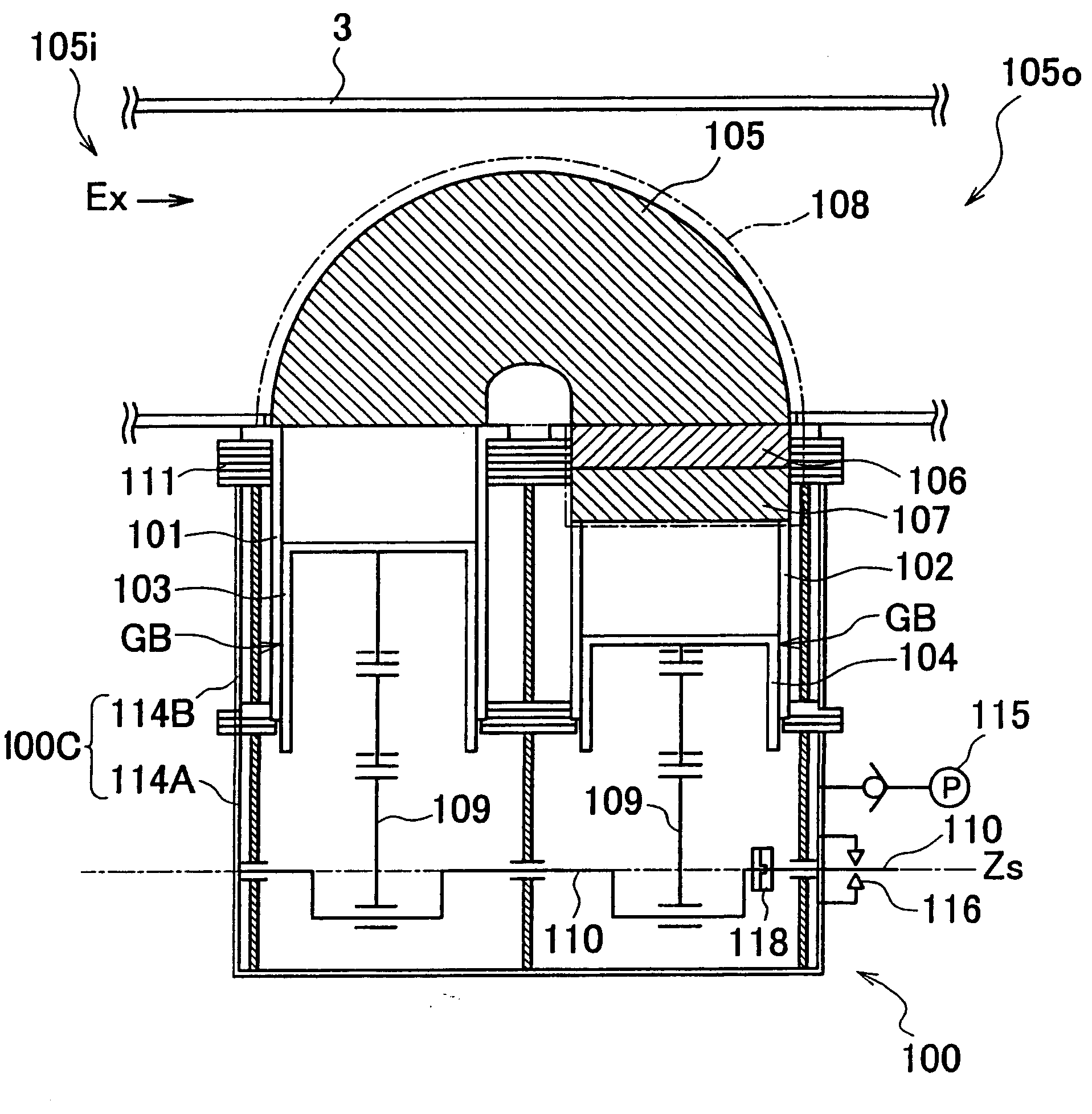
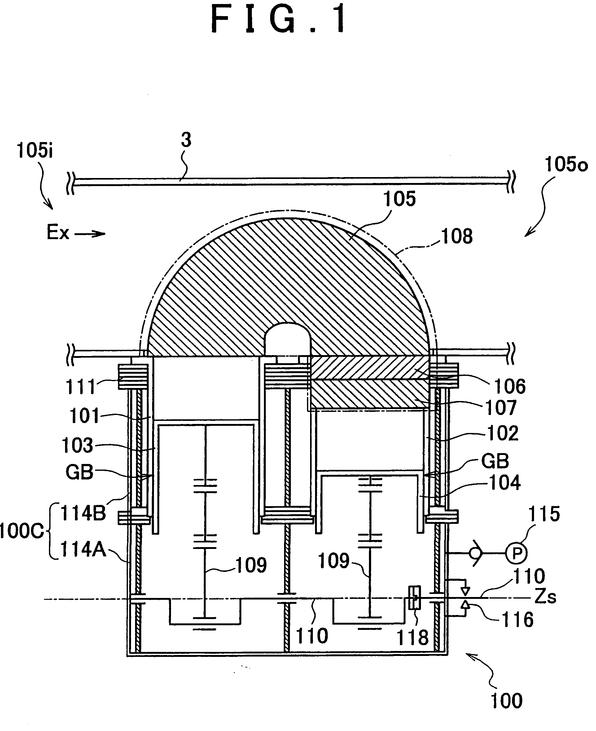
[0043]A working fluid (air in the first embodiment) is confined in the high temperature-side cylinder 101, the low temperature-side cylinder 102 and the heat exchanger 108, and realizes the Stirling cycle with the heat supplied from the heater 105 and the heat discharged from the cooler 107 to drive the Stirling engine 100. The heater 105 and the cooler 107 may be formed by bundling a plurality of tubes made of a material that has high thermal conductivity and excellent thermal resistance, for example. The regenerator 106 may be made of a porous heat storage unit. The composition of the heater 105, the cooler 107 and the regenerator 106 is not limited to this example. Specifically, the composition may be suitably selected depending on the thermal conditions of the subject from which exhaust heat is recovered, the specifications of the Stirling engine 100, etc.

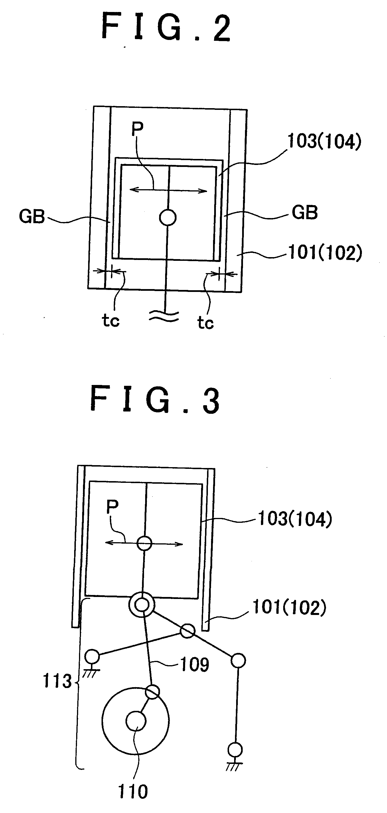
[0044]The high temperature-side piston 103 and the low temperature-side piston 104 are supported in the high temperature-side...

second embodiment

[0076]The exhaust heat recovery means transmission 5b changes the rotation speed ratio Ns / Ne by changing the gear ratio, or the speed ratio thereof. A belt-type CVT (Continuous Variable Transmission), a toroidal CVT, or a rotation speed-changing device with finite gear ratios may be used as the exhaust heat recovery means transmission 5b. The rotation speed ratio Ns / Ne of the exhaust heat recovery means transmission 5b is changed by the operation controller 30 of the

[0077]The crankshaft 110, which functions as the output shaft of the Stirling engine 100 is coupled to the input shaft 5s of the exhaust heat recovery means transmission 5b using a coupling 8. A clutch may be provided between the crankshaft 110 and the input shaft 5s as in the case of the first embodiment. The motive power from the Stirling engine 100 is transmitted to the exhaust heat recovery means transmission 5b through the coupling 8. The output shaft 1s of the internal combustion engine 1 is connected to the intern...


PUM


Abstract

An exhaust heat recovery apparatus includes a Stirling engine and a clutch. The Stirling engine produces motive power by recovering thermal energy from exhaust gas discharged from an internal combustion engine from which exhaust heat is recovered. The motive power produced by the Stirling engine is transmitted to an internal combustion engine transmission through the clutch and an exhaust heat recovery device transmission, and combined with the motive power produced by the internal combustion engine through the internal combustion engine transmission, and is output from an output shaft. If rapid acceleration is required, and the increase in the rotation speed of the Stirling engine therefore lags behind the increase in the rotation speed of the internal combustion engine, the clutch is released. With this configuration, reduction in the power output from the heat engine, from which exhaust heat is recovered, is restricted, and the degradation of the acceleration performance is minimized.

Description

BACKGROUND OF THE INVENTION[0001]1. Field of the Invention[0002]The present invention relates to an exhaust heat recovery apparatus that recovers the exhaust heat from a heat engine.[0003]2. Description of the Related Art[0004]An exhaust heat recovery apparatus is available that, using a heat engine, recovers the exhaust heat from an internal combustion engine that is mounted on a vehicle, such as a passenger car, a bus and a truck. With regard to the exhaust heat recovery apparatus used for such a purpose, external combustion engines, such as the Stirling engine, which is excellent in theoretical thermal efficiency, are used, for example. Japanese Patent Application Publication No. 2003-518458 (JP-A-2003-518458) discloses a technology in which a clutch is provided between the internal combustion engine and the Stirling engine.[0005]In an external combustion engine, such as the Stirling engine, the heat input from a heat source, such as the exhaust gas, is transferred to a working f...

Claims


Application Information

Patent Timeline
Patent Type & Authority Applications(United States)
IPC IPC(8): F02G3/00
CPCF02B41/00F02G1/043Y02T10/166F02G2254/15F02G5/02Y02E20/30Y02T10/12
Inventor SAWADA, DAISAKUMITANI, SHINICHIYAGUCHI, HIROSHI
Owner TOYOTA JIDOSHA KK
Why Eureka
Try Eureka