Optical module

a technology of optical modules and optical devices, applied in the field of optical modules, can solve the problems of difficult to ensure fabrication yield and become much more difficult to ensure yield, and achieve the effects of reducing the steps of mounting of devices, simplifying the mounting of optical devices, and high accuracy

Inactive Publication Date: 2009-04-16
HITACHI LTD
View PDF6 Cites 21 Cited by
  • Summary
  • Abstract
  • Description
  • Claims
  • Application Information

AI Technical Summary

Benefits of technology

[0008]An object of the present invention is to provide a low-cost optical module.
[0009]Consequently, an object of the embodiments of the present invention relates to an optical module used as a terminal device in wavelength multiple optical transmission and single-conductor bi-directional optical transmission for transmitting light having a plurality of wavelengths by one optical fiber, and the object is to provide an optical module capable of achieving down-sizing and high yield by largely reducing the number of mounting steps with maintaining low-loss optical properties and high reliability.
[0018]In this manner, a first feature of the present invention is that a plurality of filters are automatically aligned by only aligning a glass substrate once, thereby largely reducing steps of mounting of the devices according to the present invention.
[0019]A second feature of the present invention is that an LD and a PD are mounted in plane on an optical device mounting board, thereby largely simplifying mounting of optical devices as compared with the conventional way sterically mounting optical devices, and thus it is possible to mount highly accurately. The alignment is made by the whole optical device mounting board in an optical axis alignment, thereby reducing the number of steps as compared with the case where an optical axis alignment is individually done on each device.
[0022]According to the present invention, it is possible to provide an optical module with lower cost than conventional one.

Problems solved by technology

In addition, there is small margin in positional accuracy of the wavelength multiplexer / demultiplexer (optical multiplexer / demultiplexer), especially in angle shift, and thus highly accurate mounting is required and it is difficult to ensure fabrication yield.
Further, in consideration of extensibility, the number of optical parts and the mounting area are necessary to be two times larger and it is required to make down-sizing and highly accurate mounting of optical parts, and thus it becomes much more difficult to ensure yield.

Method used


Image

  • Optical module
  • Optical module
  • Optical module

Examples


first embodiment

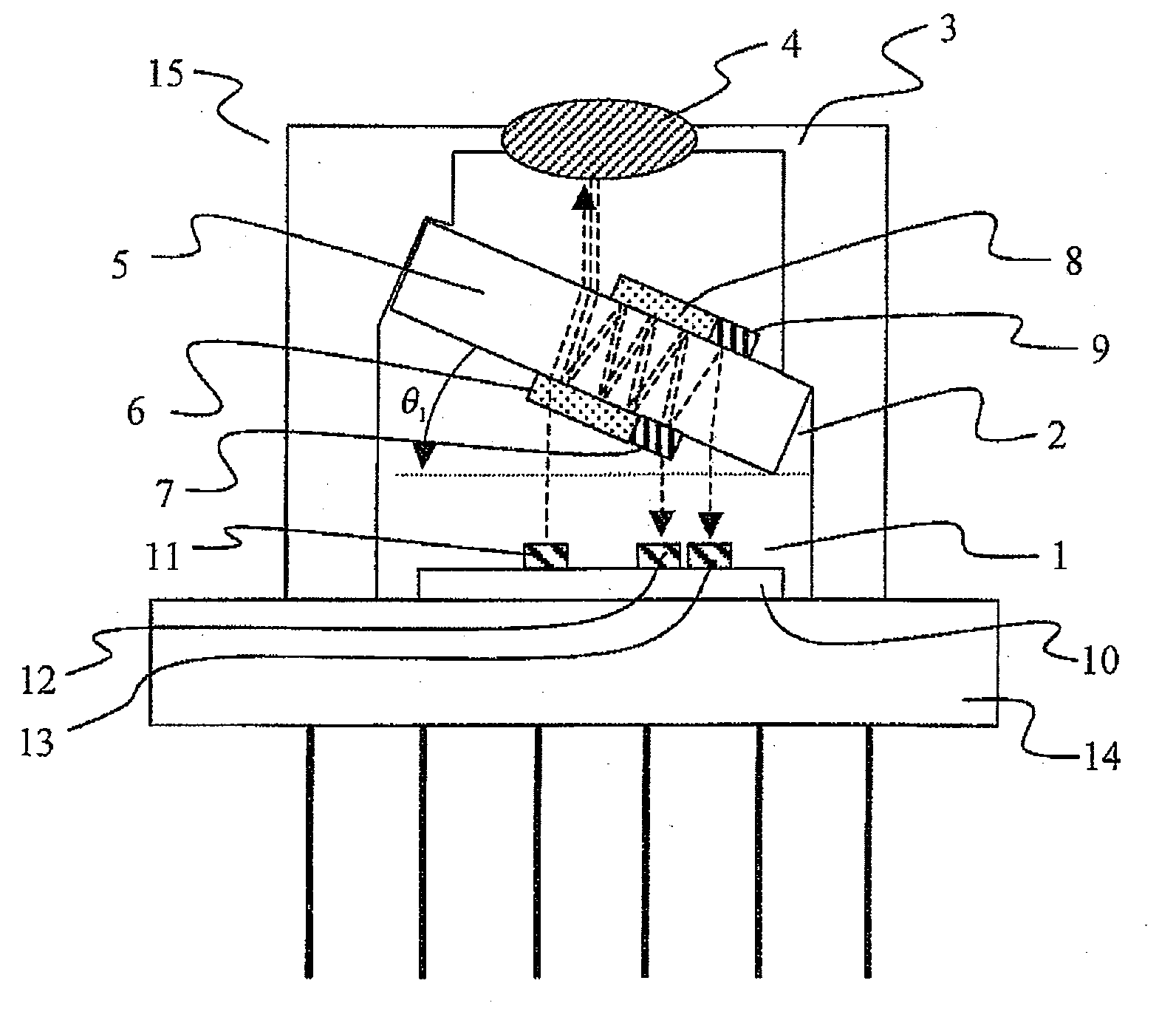
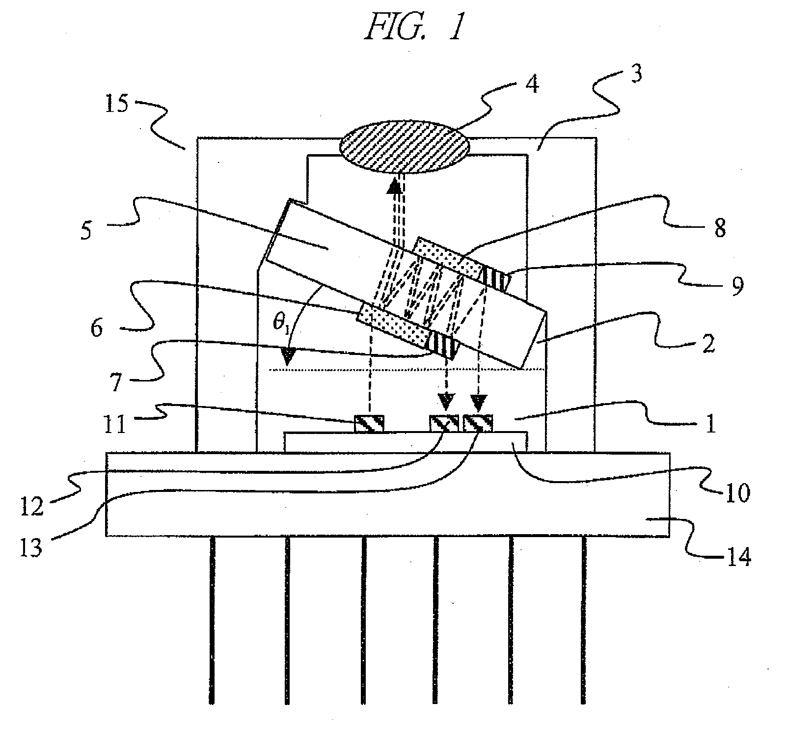
[0036]FIG. 1 is a cross-sectional view of an optical module according to a first embodiment of the present invention. FIG. 1 shows an example where the present invention is applied to a so-called optical triplexer of a bi-directional optical transmitter and receiver module using triple wavelengths.

[0037]FIG. 1 is an example of mounting on a CAN package, where the optical device mounting board 1 is mounted on the CAN stem 14 that has mounted thereon the submount 10 on which the light-emitting device 11 and the light-receiving devices 12, 13 are loaded, and the optical multiplexer / demultiplexer 2 is mounted to the CAN cap 3, so that a triplexer module 15 is configured. The optical devices 11, 12 and 13 use wavelengths λ1, λ2 and λ3, respectively, and a magnitude relation of the wavelengths is λ123. Note that, the magnitude relation of the wavelengths is not limited to this. The optical devices are arranged in ascending order of the using wavelengths in FIG. 1. A concave and a convex f...

second embodiment

[0043]FIG. 3 is a cross-sectional view of an optical module according to a second embodiment of the present invention. The present embodiment is a configuration example where the present invention is applied to a dual-wavelength single-conductor bi-directional (BIDI) module. A BIDI module 16 is, as shown in FIG. 3, similar to the first embodiment in the point that the configuration is made by the optical device mounting board 1, the optical multiplexer / demultiplexer 2, and the CAN package 3. Meanwhile, the BIDI module transmits and receives data by a single wavelength on the upstream and a single wavelength on the downstream, i.e., dual wavelengths in total, and thus the optical devices mounted on the optical device mounting board 1 are only the light-emitting device 11 and the light-receiving device 12. And, the first wavelength selective filter 6 and the mirror 8, i.e. one type for each of filter and mirror, are mounted to the optical multiplexer / demultiplexer 2.

third embodiment

[0044]FIG. 4 is a cross-sectional view of an optical module according to a third embodiment of the present invention. The present embodiment is an example where the present invention is applied to a module having a fiber attached thereto, i.e., a so-called pigtail type module. As shown in FIG. 4, the triplexer module 15 of the first embodiment of the present invention is mounted to a coaxial module chassis 21, and a fiber 22 with a ferrule is further mounted by a sleeve 23. Although a pigtail type module is shown in the present embodiment, a resectable type module can be configured by the same configuration.


PUM


Abstract

An optical module comprising: a submount provided on a CAN stem; light-emitting device and a light-receiving device; a CAN cap or package; and an optical multiplexer / demultiplexer having a wavelength selective filter on a substrate that has transmissivity to passing light and a mirror, where an extending direction of the optical multiplexer / demultiplexer is fixed in the CAN cap or the package being tilted by an angle θ (θ≠2Nπ, N=0, 1, 2, . . . ) in a two-dimensional cross section with respect to one surface of an optical device mounting board, outgoing light from the light-emitting device passes through the wavelength selective filter and the substrate and enters an optical fiber outside the cap, and outgoing light from the optical fiber enters the optical multiplexer / demultiplexer and is reflected by the wavelength selective filter and further reflected by the mirror, and then exits the optical multiplexer / demultiplexer to enter the light-receiving device.

Description

CROSS-REFERENCE TO RELATED APPLICATION[0001]The present application claims priority from Japanese Patent Application No. JP 2007-266033 filed on Oct. 12, 2007, the content of which is hereby incorporated by reference into this application.TECHNICAL FIELD OF THE INVENTION[0002]The present invention relates to an optical module. More particularly, the present invention relates to a structure of a bi-directional optical transmitter and receiver module which multiplexes or demultiplexes light having a plurality of wavelengths.BACKGROUND OF THE INVENTION[0003]In recent years, the information communication fields have been swiftly promoting data communication traffic for exchanging large-capacity data by using light. Particularly, promotion of broadband communication for data access lines has been accelerated along with the explosive growth of internet communication, and FTTH (Fiber To The Home) service has significantly recognized to be established in the market. Among optical transport ...

Claims


Application Information

Patent Timeline
Patent Type & Authority Applications(United States)
IPC IPC(8): H04J14/00H04J14/02H04B10/00H04B10/12G02B6/42H01L31/02H01S5/022
CPCG02B6/29367G02B6/4246G02B6/2938
Inventor HOSOMI, KAZUHIKOSAGAWA, MISUZUSUGAWARA, TOSHIKIAOKI, MASAHIRO
Owner HITACHI LTD
Why Eureka
Try Eureka