Piezoelectric/electrostrictive body, and piezoelectric/electrostrictive element

a piezoelectric/electrostrictive and electromechanical technology, applied in the direction of piezoelectric/electrostrictive device details, device details, niobium compounds, etc., can solve the problems of inefficient method, non-180° domain, and non-180° domain indicating a large volume change,

Inactive Publication Date: 2009-05-14
NGK INSULATORS LTD
View PDF6 Cites 9 Cited by
  • Summary
  • Abstract
  • Description
  • Claims
  • Application Information

AI Technical Summary

Benefits of technology

[0008]An object of the present invention is to provide a piezoelectric/electrostrictive body which does not require a long-tim

Problems solved by technology

In recent years, an influence on a global environment, for example, the elution of lead (Pb) due to acid rain tends to be regarded as a problem.
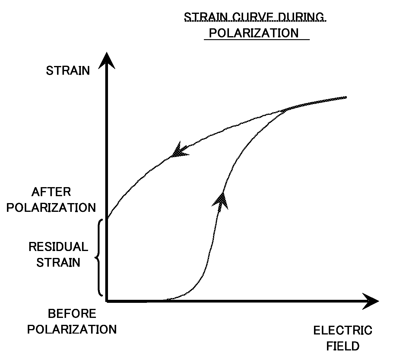
However, the rotation of the non-180° d

Method used


Image

  • Piezoelectric/electrostrictive body, and piezoelectric/electrostrictive element
  • Piezoelectric/electrostrictive body, and piezoelectric/electrostrictive element
  • Piezoelectric/electrostrictive body, and piezoelectric/electrostrictive element

Examples


example 1

[0066]The material powder of a mother material and an additive material was prepared by a usual solid phase process. As starting materials, lithium carbonate (Li2CO3), sodium tartrate (C4H5O6Na.H2O), potassium tartrate (C4H5O6K), niobium oxide (Nb2O5), tantalum oxide (Ta2O5) and manganese carbonate (MnCO3) were weighed so as to obtain compositions. The materials were mixed in alcohol by use of a ball mill for 16 hours, and the resultant mixture was dried, and then calcined at a temperature of 800° C. Next, the mixture was crushed and calcined again. After coarsely crushing the mixture, particle sizes were adjusted. At this time, the mother material powder had an average particle diameter of 0.4 to 0.5 μm, and the additive material powder had an average particle diameter of 0.4 to 0.5 μm. The additive material powder was subjected to grain growth at a temperature of 1000° C., and then coarsely crushed to obtain an average particle diameter of 1 to 2 μm by a classifier.

[0067]Thus, the...

example 2

[0079]A sample was prepared so that a mother phase of an Mn added composition was combined with an additive material phase of an Mn added composition and Bi replacing composition. As to Li, Na, K, Nb and Ta, a material similar to that of Example 1 was used. As Bi, bismuth oxide (Bi2O3) was used. In the case of the Mn added composition, as Mn, manganese dioxide (MnO2) was used. In the same manner as in Example 1, the materials excluding MnO2 were weighed, mixed and calcined. After the second calcining, MnO2 was added, and the materials were coarsely crushed to adjust particle sizes. At this time, mother material powder had an average particle diameter of 0.4 to 0.5 μm, and additive material powder also had an average particle diameter of 0.4 to 0.5 μm. The additive material powder was subjected to grain growth at a temperature of 1000° C., and then the material was coarsely crushed to obtain an average particle diameter of 1 to 2 μm by a classifier.

[0080]Thus, the mother material pow...


PUM

PropertyMeasurementUnit
Piezoelectricityaaaaaaaaaa
Electric fieldaaaaaaaaaa

Abstract

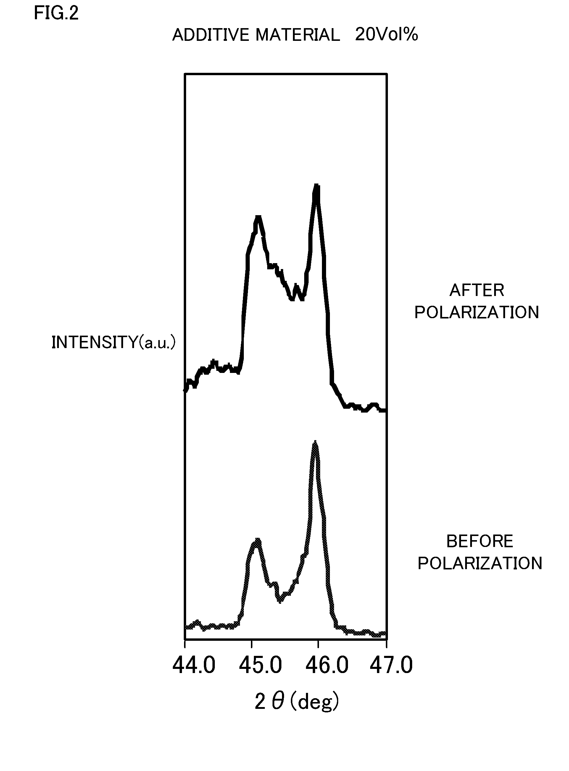
The piezoelectric/electrostrictive body is represented by a composition formula ABO3 (A includes at least one element selected from the group consisting of Li, Na and K, and B includes at least one element selected from the group consisting of Nb, Ta, Sb and Mn), and the body is formed so that a main phase is a tetragonal system, and the orientation degree of a (001) face after a polarization treatment is smaller than that of a (100) face, in a plane vertical to the applying direction of an electric field applied so as to perform the polarization treatment. The present inventive piezoelectric/electrostrictive body has a ratio between a diffraction peak intensity I001 of the (001) face and a diffraction peak intensity I100 of the (100) face of I001/I100≦1, in an X-ray diffraction pattern in the same plane after the polarization treatment.

Description

FIELD OF THE INVENTION[0001]The present invention relates to a piezoelectric / electrostrictive body, and a piezoelectric / electrostrictive element.DESCRIPTION OF THE RELATED ART[0002]Heretofore, as an element capable of controlling the micro displacement of the order of sub-microns, a piezoelectric / electrostrictive element has been known. Particularly, in the piezoelectric / electrostrictive element, a piezoelectric / electrostrictive portion constituted of a piezoelectric / electrostrictive ceramic composition (hereinafter referred to simply as the “piezoelectric ceramic material”) and an electrode portion to which a voltage is applied are laminated on a base body constituted of a ceramic material. The element is suitable for the control of the micro displacement, and has excellent characteristics such as high electromechanical conversion efficiency, high speed response, high durability and saving of power consumption. The piezoelectric / electrostrictive element can be applied to various ap...

Claims


Application Information

Patent Timeline
IPC IPC(8): H01L41/04
CPCC01G33/006H01L41/1873C01P2002/34C01P2002/52C01P2002/72C01P2006/40C04B35/495C04B2235/3201C04B2235/3203C04B2235/3251C04B2235/3255C04B2235/3262C04B2235/3267C04B2235/449C04B2235/5436C04B2235/5445C04B2235/765C04B2235/768C04B2235/783C04B2235/785C04B2235/786C04B2235/787C04B2235/79C04B2235/80C01G35/006H10N30/8542
Inventor YAMAGUCHI, HIROFUMIOZAWA, SHUICHI
Owner NGK INSULATORS LTD
Why Eureka
Try Eureka