Ceramic sintered body

a technology of ceramic and sinter body, which is applied in the field of ceramic sinter body, can solve the problems of difficult machine and high price of sic sinter body, and achieve the effects of excellent cutting performance, excellent breakage resistance and wear resistance, and high cutting efficiency

Active Publication Date: 2014-08-28
NGK SPARK PLUG CO LTD
View PDF2 Cites 9 Cited by
  • Summary
  • Abstract
  • Description
  • Claims
  • Application Information

AI Technical Summary

Benefits of technology

[0083](1) The ceramic sintered bodies of S3 to 6, 10 to 12, 14, 15, 17, 18, and 30 to 36 had excellent breakage resistance and wear resistance.
[0084]In light of the above results, the ceramic sintered bodies of S3 to 6, 10 to 12, 14, 15, 17, 18, and 30 to 36 were confirmed to be useful for finishing of heat resistant super alloys. Specially, the above ceramic sintered bodies showed excellent cutting performance in finishing at the cutting speed of 240 m / min or more. Accordingly, the use of the above ceramic sintered bodies enables highly efficient cutting of heat resistant super alloys. The use of the above ceramic sintered bodies also enables finished surface conditions to be improved.

Problems solved by technology

Heat resistant super alloys have excellent heat resistance, while they are very difficult to machine.
However, there is a problem in that SiC whiskers are expensive.

Method used


Image

  • Ceramic sintered body
  • Ceramic sintered body
  • Ceramic sintered body

Examples


example 1

1. Manufacturing Method of Ceramic Sintered Body

[0040]The following three types of material powders were weighed each in a predetermined amount, inserted together with acetone into a mill made of resin, and ground using alumina balls for 48 hours, to thereby obtain a slurry.

[0041]Alumina powders with an average particle diameter of 0.4 μm

[0042]Tungsten carbide powders with an average particle diameter of 0.1 to 1.5 μm

[0043]Zirconia powders with an average particle diameter of 0.6 μm (including 0 to 8 mol % yttria as a stabilizer)

[0044]The obtained slurry was warmed in hot water to remove ethanol and sieved to obtain mixed powders. The mixed powders were inserted into a carbon mold and hot-press sintered to obtain a ceramic sintered body. The conditions for the hot-press sintering were as follows:

[0045]Sintering temperature: 1650° C.

[0046]Sintering time: 2 hours

[0047]Pressure: 30 MPa

[0048]Atmosphere: Ar gas

[0049]In the above-described manufacturing method, the compounding ratio of th...

example 2

1. Manufacturing Method of Joined Body 5

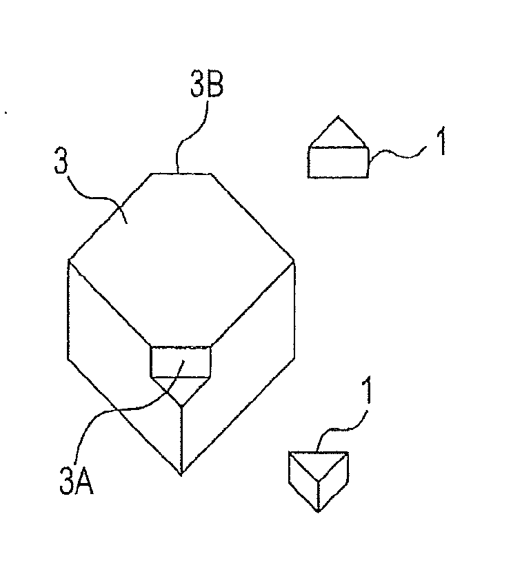
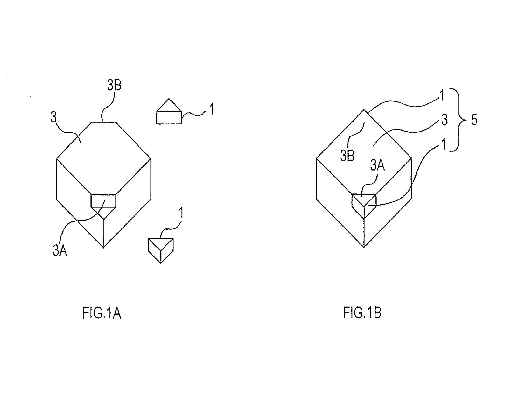
[0085]First, as shown in FIG. 1A, a first member 1 made of the ceramic sintered body S5 of the above-described Example 1 and a second member 3 made of super hard alloy (made of WC and a cobalt binder) were manufactured individually. The first member 1 had a triangular prismatic shape. The second member 3 basically had a rectangular parallelepiped shape having cutouts in proportion to the first member 1 at its two vertices 3A and 3B.

[0086]Next, as shown in FIG. 1B, the first member 1 was joined to each of the vertices 3A and 3B of the second member 3 by brazing to thereby complete a joined body 5. The joined body 5 had a rectangular parallelepiped shape that corresponds to DNGA 150408.

2. Evaluation of Joined Body 5 (Part 1)

[0087](1) Test Conditions

[0088]Finishing was performed under the following conditions using the joined body 5 as a tip, when the portion of the joined body 5 that mainly contacted the cutting workpiece was the first member 1....


PUM

PropertyMeasurementUnit
average particle diameteraaaaaaaaaa
particle diameteraaaaaaaaaa

Abstract

A ceramic sintered body includes tungsten carbide, zirconia, and alumina. The content of the tungsten carbide is 20 to 50 vol %, and the content of the zirconia is 5 to 25 vol %. The crystal phase of the zirconia is a tetragonal crystal or a mixture of tetragonal and monoclinic crystals. The ceramic sintered body does not substantially include Ti compounds. The average particle diameter of the tungsten carbide, the average particle diameter of the zirconia, and the average particle diameter of the alumina are all 1 μm or less.

Description

CROSS-REFERENCE TO RELATED APPLICATIONS[0001]This international application claims the benefit of Japanese Patent Application No. 2012-145676 filed Jun. 28, 2012 in the Japan Patent Office, and the entire disclosure of Japanese Patent Application No. 2012-145676 is incorporated herein by reference.TECHNICAL FIELD[0002]The present invention relates to a ceramic sintered body that can be used for, for example, a cutting tool and the like.BACKGROUND ART[0003]Heat resistant super alloys have excellent heat resistance, while they are very difficult to machine. Therefore, tools used for cutting heat resistant super alloys are required with high physical properties and heat resistance. Alumina-based materials that contain silicon carbide whiskers (hereafter referred to as SiC whiskers) have high hardness, toughness, and heat resistance, and tools made of such materials demonstrate superior performance in cutting heat resistant super alloys to that of other tools. However, there is a proble...

Claims


Application Information

Patent Timeline
Patent Type & Authority Applications(United States)
IPC IPC(8): C04B35/106C04B35/56
CPCC04B35/106C04B35/5626B23B2226/18C04B35/119C04B35/645C04B2235/3217C04B2235/3225C04B2235/3246C04B2235/3843C04B2235/3847C04B2235/3856C04B2235/3886C04B2235/5436C04B2235/5445C04B2235/6562C04B2235/72C04B2235/85C04B2235/96C04B2235/9607C04B35/48C04B2235/3244C04B37/02Y10T428/268Y10T407/27
Inventor MOTEKI, JUNKATSU, YUSUKEMITSUOKA, TAKESHI
Owner NGK SPARK PLUG CO LTD
Why Eureka
Try Eureka