System and method for signal level detection

a signal level and detection circuit technology, applied in pulse manipulation, pulse technique, instruments, etc., can solve the problems of affecting the accuracy of these measurements, and affecting the response time, so as to reduce the bandwidth requirements, improve the accuracy, and reduce the effect of vulnerability

Active Publication Date: 2009-05-14
MACOM CONNECTIVITY SOLUTIONS LLC
View PDF1 Cites 18 Cited by
  • Summary
  • Abstract
  • Description
  • Claims
  • Application Information

AI Technical Summary

Benefits of technology

[0012]A signal level detection system and method are provided that address the above-mentioned problems associated with conventional designs. The present invention level detector improves accuracy by reducing the bandwidth requirements of the linear analog blocks, making the level detector less susceptible to the frequency response of the channel and circuit being measured. The reduced bandwidth design inherently requires less power. The digital implementation of the level detector permits a simple means of calibrating-out common mode offsets. Separate positive and negative peak detection automatically calibrates out differential offsets. Sufficiently long time constants are implemented through integration enabled with digital counters instead of capacitors. The use of counters instead of an integration capacitor reduces the size of the level detector circuit. Implementation in digital circuits is easily repeated (portable), efficient in that little quiescent current is required, and is less sensitive to location and routing.

Problems solved by technology

Various factors that tend to degrade the accuracy of these measurements include device mismatches, changes in temperature, varying bandwidths, and signal content.
However, use of feedback is problematic for high speed signals, effectively forcing response times to be too slow.
Various feedforward techniques allow faster response time, but these techniques require large internal devices, consuming die area or use of external components, and the measurements are not sufficiently repeatable.
Practically, when the input becomes negative, the output of the operational amplifier can easily approach the negative supply voltage (not shown), causing saturation.
Since it takes a finite time to recover from saturation, the frequency response of the circuit is impaired.
The use of non-linear circuit devices (i.e., a diode) makes signal level measurements very susceptible to variations in temperature and device process variations.
Further, the architecture is not easily portable from one device to another.
The high speed of signals, combined with the need to charge a large capacitor, causes conventional detector circuits to consume a large amount of power.
However, as circuit dimensions get smaller, the relative size of these large-value storage capacitors is becoming larger.

Method used


Image

  • System and method for signal level detection
  • System and method for signal level detection
  • System and method for signal level detection

Examples


Embodiment Construction

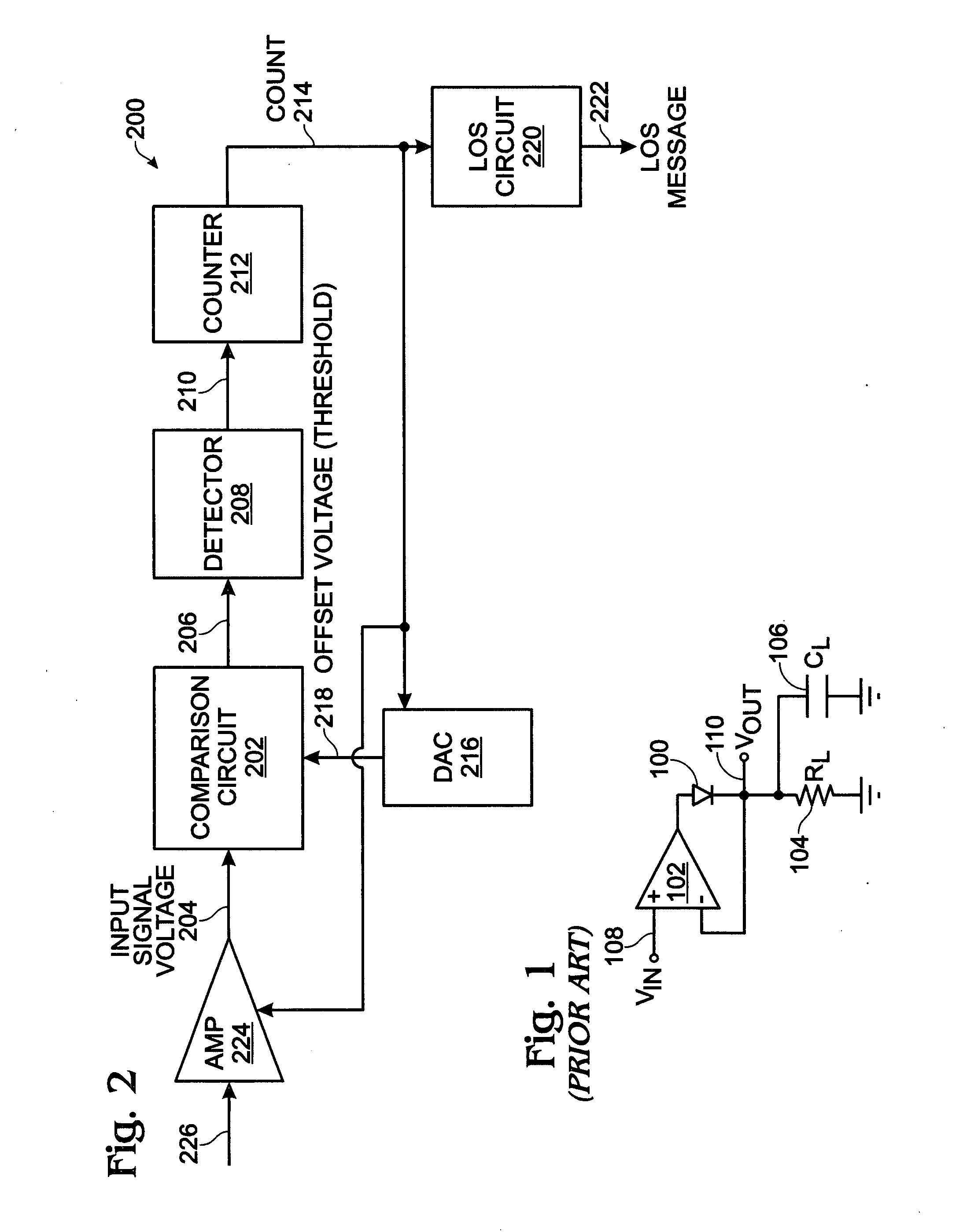
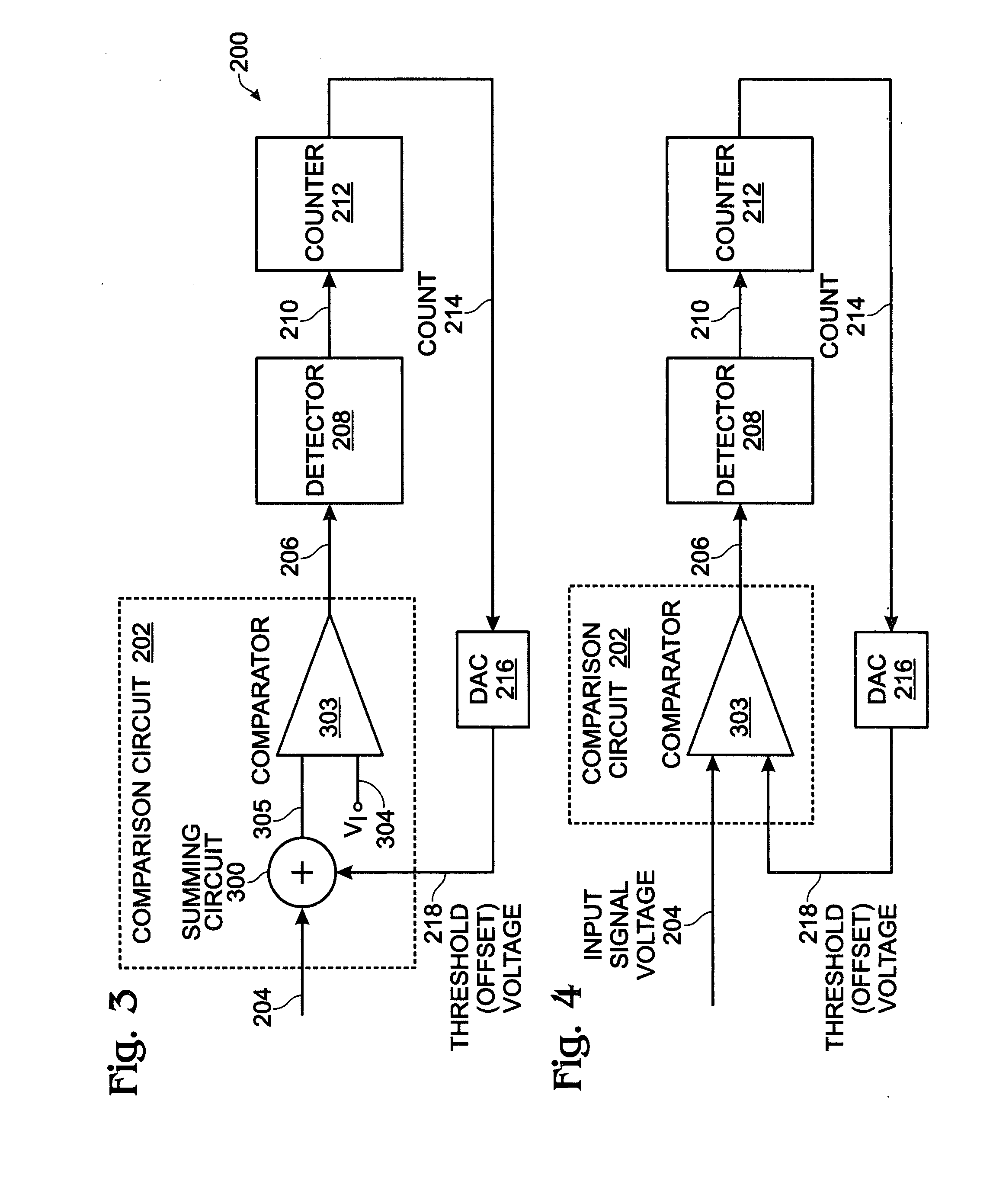
[0028]FIG. 2 is a schematic block diagram depicting an electronic signal level detection system. The system 200 comprises a comparator 202 having a first input on line 204 to receive an analog input signal having a variable voltage. The comparison circuit 202 compares the input signal voltage to a threshold on line 218 and supplies a comparator signal at an output on line 206 for input signal voltages exceeding the threshold. A detector 208 has an input on line 206 to receive the comparator signal and an output on line 210 to supply detection signals responsive to receiving comparator signals in a periodic first time frame.

[0029]A counter 212 has an input on line 210 to receive the detection signals and an output on line 214 to supply a count in a periodic second time frame following the first time frame. More explicitly, the counter 212 increments the count in response to receiving a detection signal in the first time frame, and decrements the count in response to not receiving a d...


PUM


Abstract

An electronic signal level detection system and method are provided. The method receives an analog input signal having a variable voltage and compares the input signal voltage to a threshold. A detection signal is generated for input signal voltages exceeding the threshold in a periodic first time frame. In a second periodic time frame (following the first time frame), a count is updated in response to the generated detection signals. The count is used to create a metric representative of the difference between the input signal voltage and the threshold. The count is incremented in response to the generating a detection signal (“1”) in the first time frame, and decremented in response to not generating a detection signal (“0”) in the first time frame.

Description

BACKGROUND OF THE INVENTION[0001]1. Field of the Invention[0002]This invention generally relates to signal level detection circuitry and, more particularly, to a system and method for an improved electrical signal level detection circuit and associated detection method.[0003]2. Description of the Related Art[0004]An electrical signal level detection function is commonly achieved using an analog peak detector, forward biasing of a diode, bipolar base-emitter (BE) junction, or FET-charged capacitor until the DC voltage of the capacitor approaches the peak level of the AC signal. A large time constant is achieved by maximizing the size of the capacitor and minimizing the discharge current. Various factors that tend to degrade the accuracy of these measurements include device mismatches, changes in temperature, varying bandwidths, and signal content. One approach to addressing these inaccuracies involves the use of conventional closed loop methods. However, use of feedback is problemati...

Claims


Application Information

Patent Timeline
Patent Type & Authority Applications(United States)
IPC IPC(8): H03G3/20H03K5/1532H03M1/70
CPCG01R19/04G01R19/2506H03G3/001H03G3/3042H03M3/49H03M3/43H03M3/456H03M3/486H03K5/1532
Inventor BROWN, MATTHEW DOUGLASHOOD, SHELDON JAMESFORTIER, GUY JACQUEBLAKEY, STAN HARRY
Owner MACOM CONNECTIVITY SOLUTIONS LLC
Why Eureka
Try Eureka