Cryotomography X-Ray Microscopy State

a cryotomography and state technology, applied in the field of microscopy, can solve the problems of inconvenient manual procedures, limited resolution of uv-visible light microscopy, and lack of precise temperature control

Inactive Publication Date: 2009-05-21
RGT UNIV OF CALIFORNIA
View PDF2 Cites 13 Cited by
  • Summary
  • Abstract
  • Description
  • Claims
  • Application Information

AI Technical Summary

Problems solved by technology

However, UV-visible light microscopy has limited resolution.
These methods lack precise temperature control and may require gas stream rates that could disturb the sample during imaging.
However, these techniques require tedious and time-consuming manual procedures and may introduce additional error into the resulting image.
Additionally, the use of fiducial markers may interfere with the sample.

Method used


Image

  • Cryotomography X-Ray Microscopy State
  • Cryotomography X-Ray Microscopy State
  • Cryotomography X-Ray Microscopy State

Examples


example 1

Imaging of Saccharomyces cerevisiae

[0026]The budding yeast, Saccharomyces cerevisiae was imaged using an x-ray microscope and a cyro tomographic microscope stage. Saccharomyces cerevisiae were grown with rotary shaking at 25 degrees C. in liquid YPD medium (1% yeast extract, 2% bapto peptone, and 2% glucose). Just prior to imaging, they were loaded into a 10 micron-diameter capillary from the beveled tip end of the capillary using an Eppendorf microinjection apparatus. The yeast were examined in a light microscope then rapidly frozen with a blast of liquid nitrogen cooled helium gas and placed in the x-ray microscope stage.

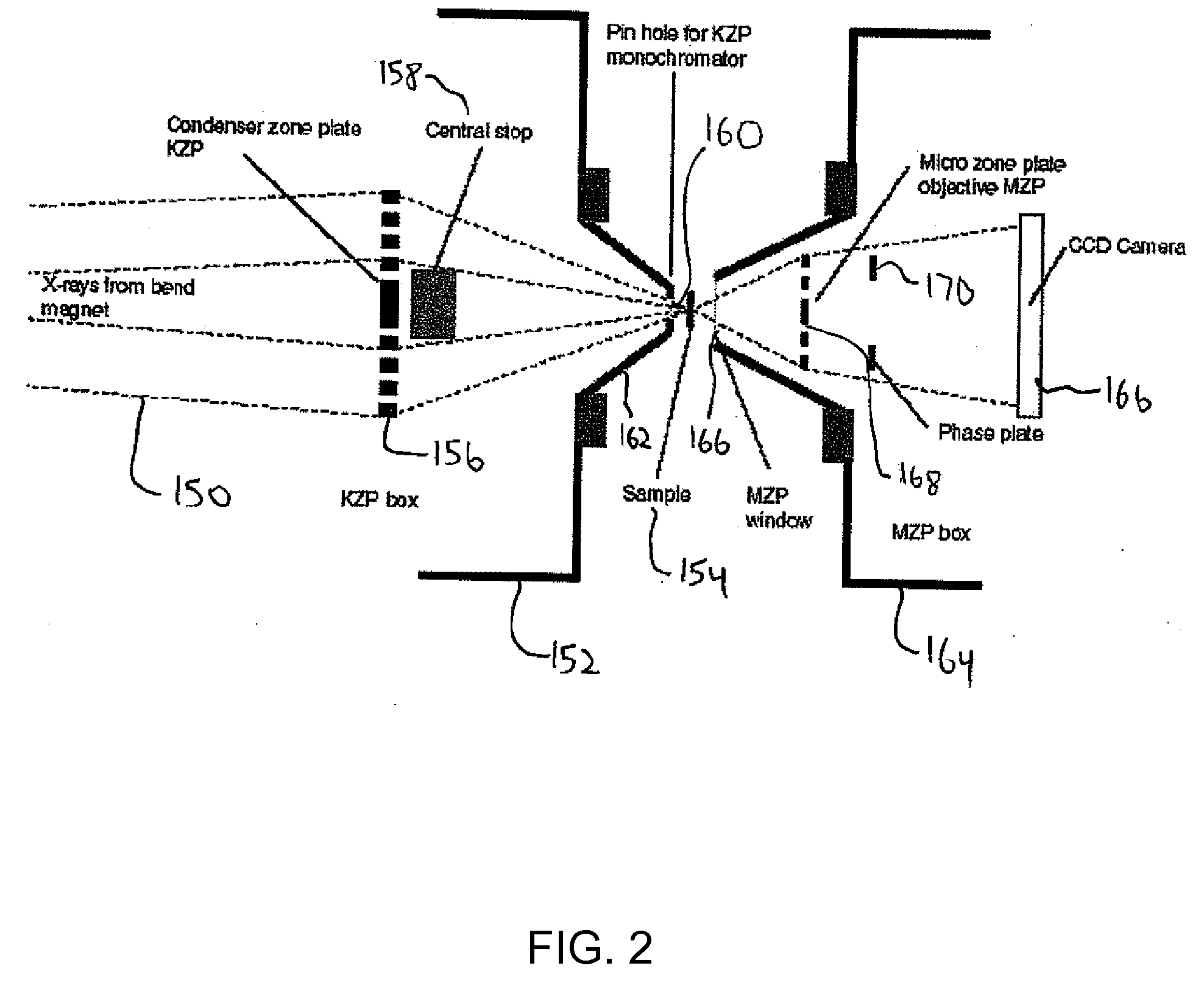
[0027]A soft x-ray source generated by a bend magnet at the Advanced Light Source at Lawrence Berkeley National Laboratory was used. A Fresnel zone plate having 9 mm diameter with an outermost zone width of 55 nm and a focal length of 205 mm at 517 eV photon energy was used as a condenser. A Fresnel zone plate having a 40 micron diameter, within outermost zone wi...


PUM


Abstract

An x-ray microscope stage enables alignment of a sample about a rotation axis to enable three dimensional tomographic imaging of the sample using an x-ray microscope. A heat exchanger assembly provides cooled gas to a sample during x-ray microscopic imaging.

Description

CROSS-REFERENCE TO RELATED APPLICATIONS[0001]This application claims priority to U.S. Patent Provisional Application 60 / 673,017, filed Apr. 20, 2005, which is incorporated by reference herein. This application is also related to Patent Application PCT / US05 / , ______ Attorney docket no. IB-1981 PCT, filed Apr. 20, 2006.STATEMENT OF GOVERNMENT INTEREST[0002]The invention described and claimed herein was made in part utilizing funds supplied by the U.S. Department of Energy under Contract Number DE-AC03-76SF00098 and by the National Institutes of Health under Grant Number R01 GM63948-03. The U.S. government has certain rights in this invention.TECHNICAL FIELD[0003]The present invention relates generally to the field of microscopy, and, more specifically, to a precision specimen stage for use with high resolution x-ray microscopy.BACKGROUND ART[0004]Among the most commonly used microscopic techniques for imaging whole cells or other materials in biology or materials science are UV-visibl...

Claims


Application Information

Patent Timeline
Patent Type & Authority Applications(United States)
IPC IPC(8): G02B21/26
CPCG21K7/00
Inventor LE GROS, MARKLARABELL, CAROLYN A.
Owner RGT UNIV OF CALIFORNIA
Why Eureka
Try Eureka