Eureka AIR delivers breakthrough ideas for toughest innovation challenges, trusted by R&D personnel around the world.

Systems and Methods for Removing Materials From Flue Gas Via Regenerative Selective Catalytic Reduction

a technology of selective catalytic reduction and flue gas, which is applied in the direction of combustible gas purification/modification, separation processes, lighting and heating apparatus, etc., can solve the problems of not having to meet unacceptable thermal inefficiency when carried out, nor the need for costly design changes to implement, so as to facilitate the performance of subsequent cycles and the level of ammonia slip is not excessively high

Inactive Publication Date: 2009-05-21
BABCOCK POWER ENVIRONMENTAL INC (US)
View PDF21 Cites 37 Cited by
  • Summary
  • Abstract
  • Description
  • Claims
  • Application Information

AI Technical Summary

Benefits of technology

"The present invention provides systems and methods for removing materials from flue gas using regenerative selective catalytic reduction (RSCR). The RSCR process is efficient and does not require costly design changes or thermal inefficiencies. The RSCR apparatus includes heat transfer areas and catalyst areas that work together to remove NOx from the gas. The process involves introducing the gas into the apparatus, heating it with residual heat, and then passing it through multiple catalyst areas for conversion. The RSCR process also provides heat for the performance of subsequent cycles of the process. Compared to conventional selective catalytic reduction (SCR) processes, the RSCR process has higher heat transfer and heat recovery levels, and lower ammonia slip levels. The RSCR apparatus can also include means for reducing CO in the mixed flue gases. The patent text also describes a method for reducing contaminants in a mixed gas by introducing a predetermined concentration of reactant and causing the mixed gas to be treated within the RSCR apparatus. The treated gas is then expelled from the apparatus."

Problems solved by technology

Such systems and methods advantageously enable high removal efficiencies, yet they neither necessitate costly design changes to implement nor encounter unacceptable thermal inefficiencies when carried out.

Method used


Image

  • Systems and Methods for Removing Materials From Flue Gas Via Regenerative Selective Catalytic Reduction
  • Systems and Methods for Removing Materials From Flue Gas Via Regenerative Selective Catalytic Reduction
  • Systems and Methods for Removing Materials From Flue Gas Via Regenerative Selective Catalytic Reduction

Examples


Embodiment Construction

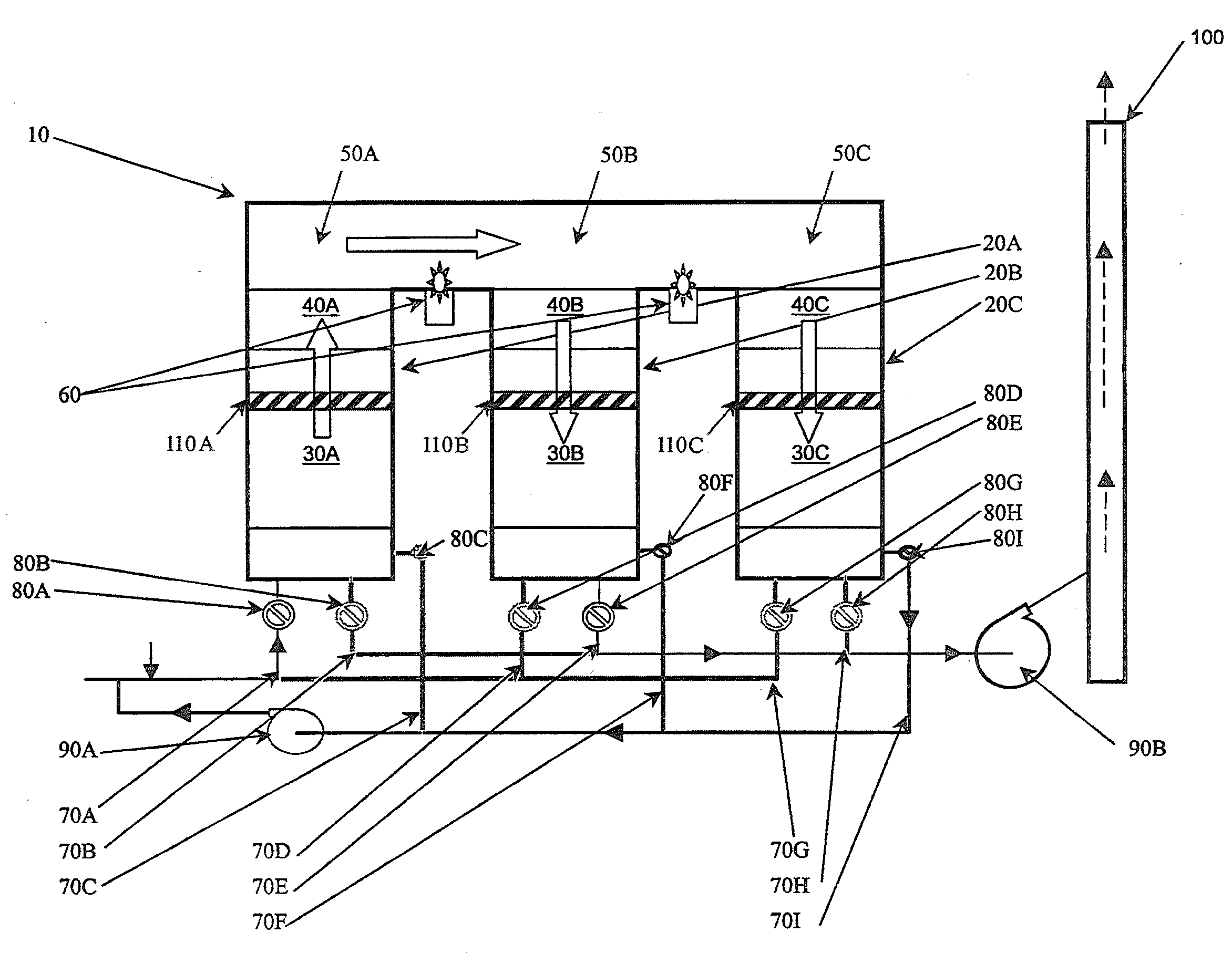
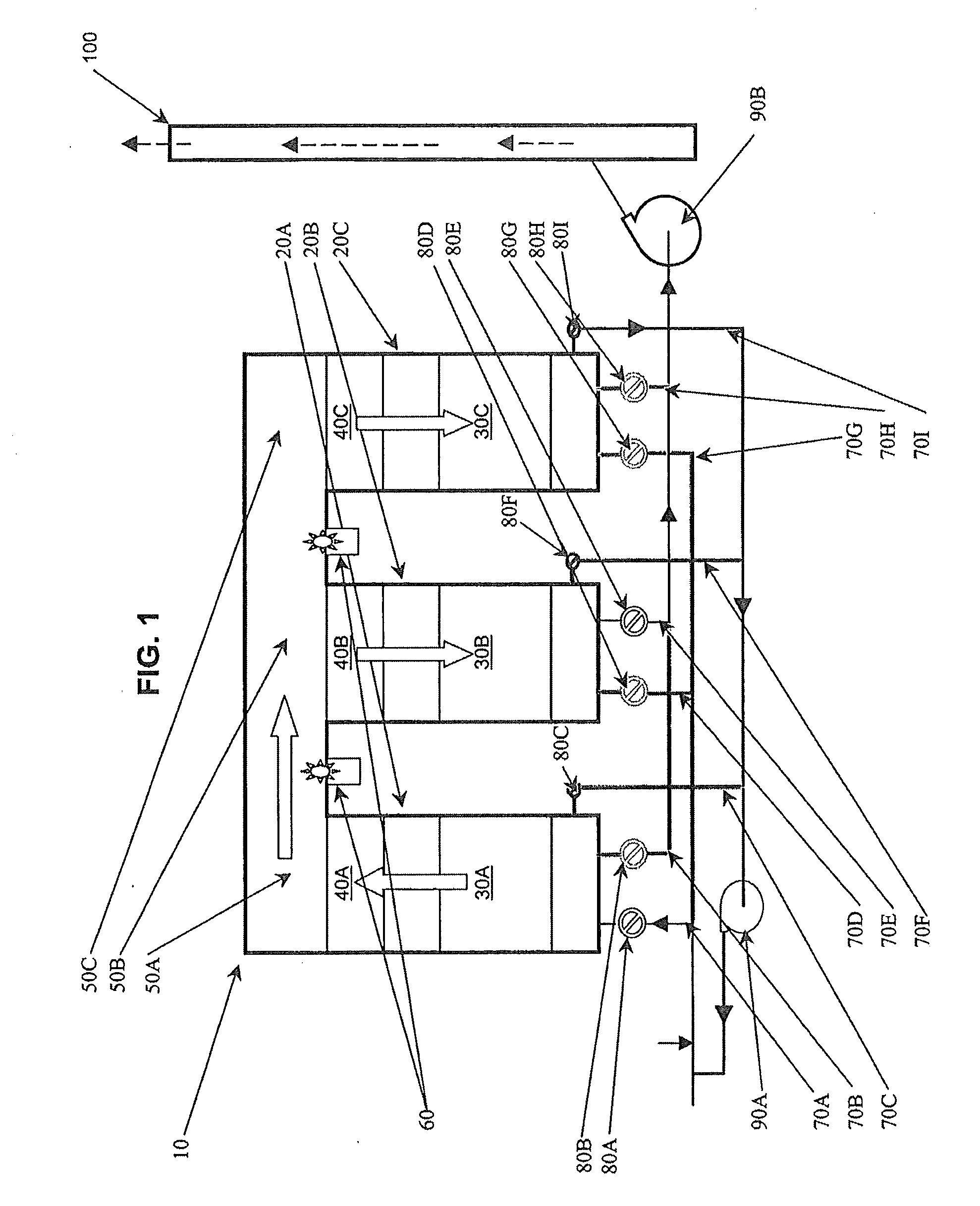
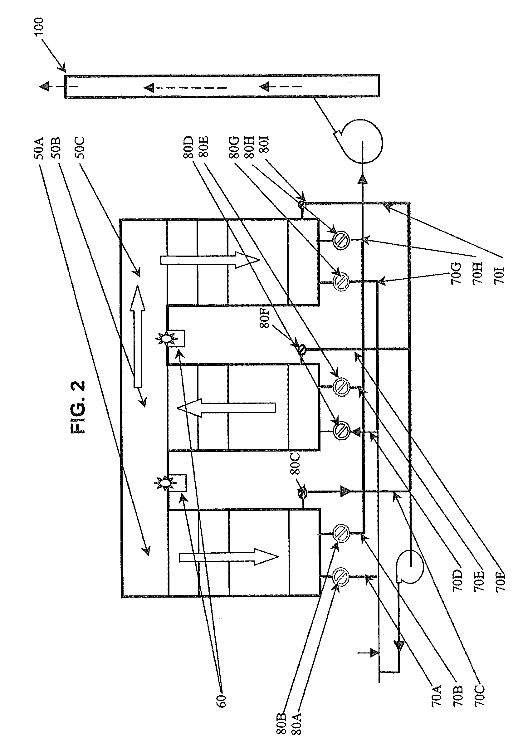
[0029]FIGS. 1-3 depict a regenerative selective catalytic reduction (RSCR) apparatus 10. The RSCR apparatus 10 is sited within other industrial equipment (not shown) that outputs airborne materials (e.g., flue gas) into the environment. Examples of such industrial equipment include, but are not limited to, high-temperature combustion equipment and power plant equipment. The specific location of the apparatus 10 within such industrial equipment can vary; however, according to a currently preferred embodiment of the present invention, the RSCR apparatus is located at the so-called “tail end” (i.e., “cold side”) of the industrial equipment. Other exemplary locations for the RSCR apparatus include, but are not limited to so-called “hot side” locations, e.g. “hot side, low dust.”

[0030]The RSCR apparatus 10 includes a plurality of chambers (also known as canisters, housings, units or segments) 20 into and out of which contaminant-containing (e.g., NOx-containing) gas flows to be heated or...


PUM

PropertyMeasurementUnit
temperatureaaaaaaaaaa

Abstract

Regenerative selective catalytic reduction (RSCR) systems and processes are provided whereby NOx and CO levels in gases are reduced by mixing the gas with a reactant and then introducing the gas into an RSCR apparatus for treatment that entails heating the gas, causing the gas to undergo one or more catalytic reactions, and then directing the gas through a heat transfer area, to which the gas provides heat for use in connection with successive cycles of the RSCR process.

Description

CROSS-REFERENCE TO RELATED APPLICATIONS[0001]This application claims benefit of priority from U.S. Provisional Application Ser. No. 61 / 056,310, filed May 27, 2008, and is a continuation in part of U.S. application Ser. No. 11 / 938,665 filed Nov. 12, 2007, which is a continuation of U.S. application Ser. No. 10 / 957,499, filed Sep. 30, 2004, now U.S. Pat. No. 7,294,321, each of which is incorporated by reference herein in its entirety.FIELD OF THE INVENTION[0002]The present invention relates to systems and methods for removing materials from flue gas, and, more particularly, to systems and methods for flue gas denitrification (i.e., for removing nitrogen oxides from flue gas) via regenerative selective catalytic reduction (RSCR).BACKGROUND OF THE INVENTION[0003]High-temperature combustion processes and other like technologies serve vital roles in industry; however, often an unfortunate by-product of such processes is the generation and release into the atmosphere of contaminants within...

Claims


Application Information

Patent Timeline
Patent Type & Authority Applications(United States)
IPC IPC(8): B01D53/94B01D53/56B01D53/62
CPCB01D53/8625B01D53/90B01D53/9477B01D2251/2062B01D2251/208B01D2257/708B01D2255/20723B01D2255/20776B01D2257/404B01D2257/502B01D2255/20707
Inventor ABRAMS, RICHARD F.HAROLD, JOHN ROBERT
Owner BABCOCK POWER ENVIRONMENTAL INC (US)
Why Eureka
Eureka Blog
Learn More