Movable-body apparatus, exposure apparatus, exposure method, and device manufacturing method

Inactive Publication Date: 2009-05-28
NIKON CORP
View PDF7 Cites 10 Cited by
  • Summary
  • Abstract
  • Description
  • Claims
  • Application Information

AI Technical Summary

Benefits of technology

[0034]Further, in a lithography process, an object is exposed by using any one of the first to the third exposure methods of the present invention, a pattern is formed on the object, treatments (e.g., development, etching, etc.) are applied to the object on which the pattern is formed

Problems solved by technology

However, due to finer patterns which come from higher integration of semiconductor devices, a positional controllability of stages with a higher precision is required, and now, a short-term fluctuation of measured values caused by a fluctuation of atmospheric temperature on optical paths of beams of laser interferometers has become non-negligible.
However, for encoders describe

Method used


Image

  • Movable-body apparatus, exposure apparatus, exposure method, and device manufacturing method
  • Movable-body apparatus, exposure apparatus, exposure method, and device manufacturing method
  • Movable-body apparatus, exposure apparatus, exposure method, and device manufacturing method

Examples


first embodiment

[0046]Hereinafter, we describe a first embodiment of the present invention with FIGS. 1 to 3.

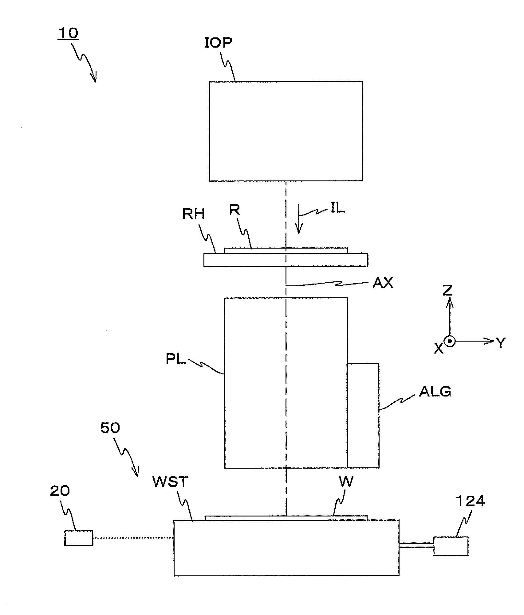
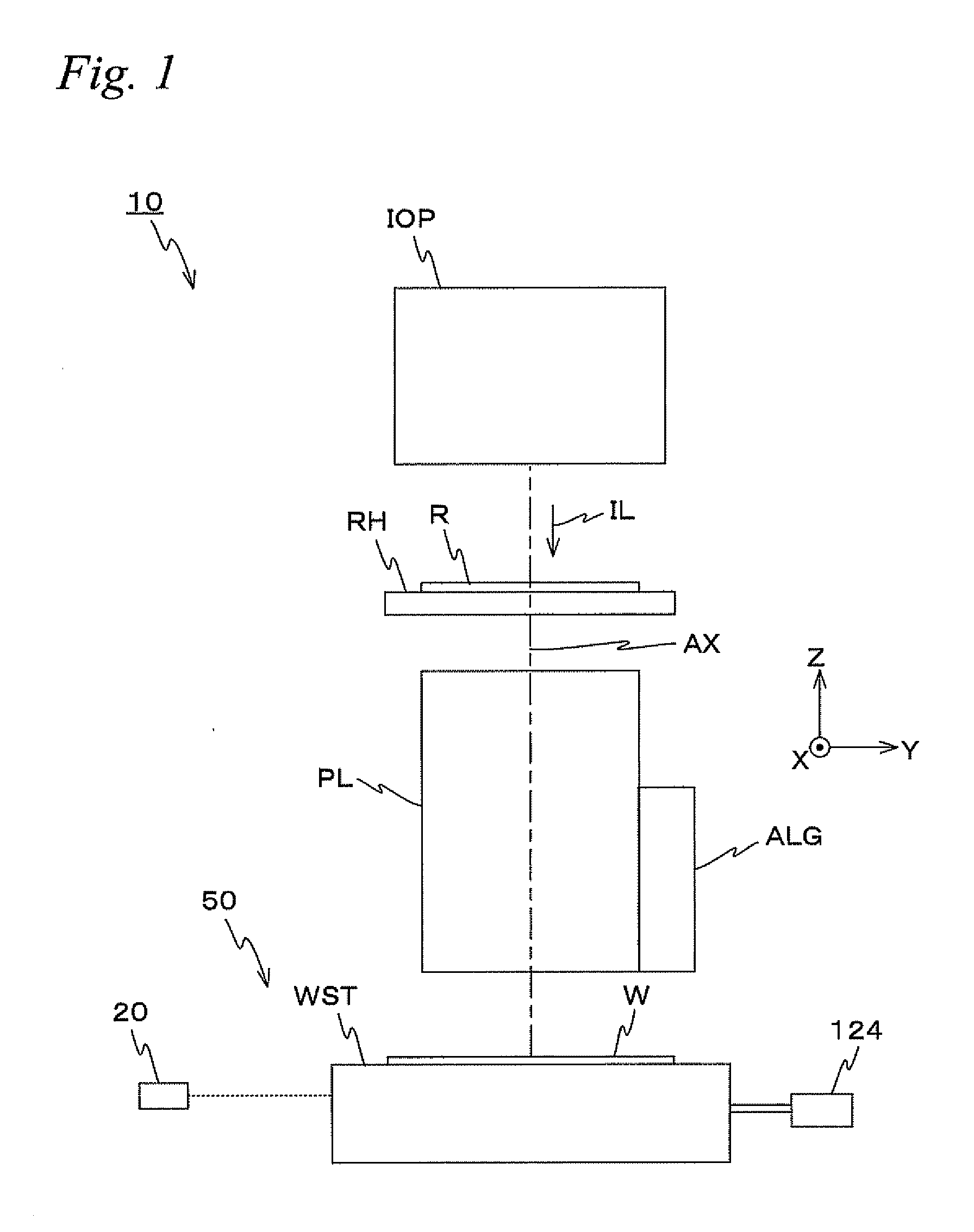
[0047]FIG. 1 shows a schematic constitution of an exposure apparatus 10 in the first embodiment. The exposure apparatus 10 is a projection exposure apparatus of the one-shot exposure type such as a stepper etc. As described later, in the present embodiment, a projection optical system PL is arranged, and hereinafter, it is supposed that a direction parallel to the optical axis AX of the projection optical system PL is the Z-axis direction, the horizontal direction in FIG. 1 within a plane orthogonal to the Z-axis, a direction orthogonal to the Z-axis and the Y-axis (a orthogonal direction on the page surface of FIG. 1) is the Y-axis direction, and rotation (tilt) directions around the X-axis, the Y-axis, and the Z-axis are, respectively, the θx, θy, and θz directions.

[0048]The exposure apparatus 10 includes an illumination unit IOP, a reticle holder RH that holds a reticle R, a projection op...

second embodiment

[0082]Next, we describe a second embodiment of the present invention with FIGS. 4A and 4B. Here, for constituent parts identical to or equivalent to those in the first embodiment described above, the same marks are used and their explanations are simplified or omitted.

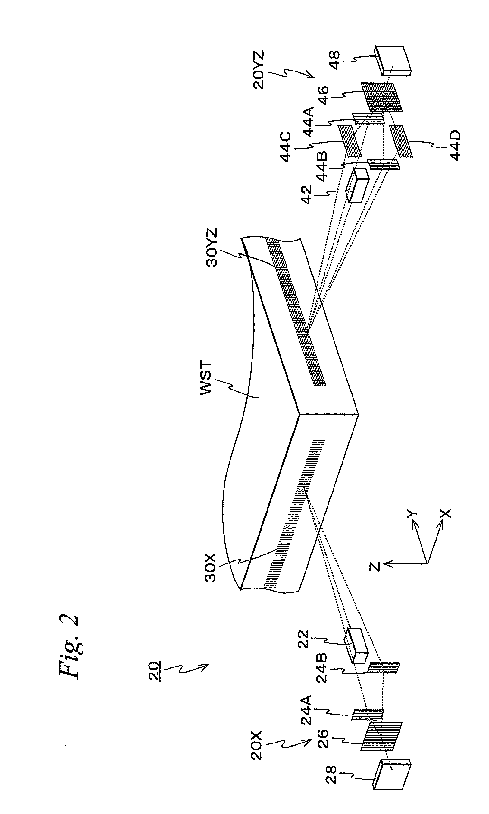
[0083]FIG. 4A shows a perspective view corresponding to FIG. 2 in the first embodiment. As shown in FIG. 4A, in the present embodiment, a reflection plane 134 is arranged on the −Y side end of the wafer stage WST and the constitution of a main body of an encoder 20Y′ is different from that of the encoder 20X in the first embodiment. The reflection plane 134 is formed by vapor-depositing, e.g., aluminum etc. on a plane tilted by 45 degrees to the XY plane formed at the −Y end of the wafer stage WST. In other words, the reflection plane 134 crosses the XY plane on the YZ plane at an acute angle. Further, above the wafer stage WST, a first fixed scale 135 in a plate shape with the Y-axis direction as its longitudinal dire...

third embodiment

[0091]Next, we describe a third embodiment of the present invention with FIGS. 5A and 5B. Here, for constituent parts identical to or equivalent to those in the second embodiment described above, the same marks are used and their explanations are simplified or omitted.

[0092]As shown in FIG. 5A, in the present embodiment, a pattern with a periodic direction in the X-axis direction (e.g., a diffraction grating) is formed on the reflection plane 134 of the wafer stage WST, a fixed scale 135′ on which a pattern with a periodic direction in the X-axis direction (e.g., diffraction grating) is formed and which has the Y-axis direction as its longitudinal direction is arranged substantially parallel to the XY plane above the wafer stage WST, and furthermore, the constitution of the main body of the encoder 20X′ is different from the first and second embodiments described above.

[0093]The fixed scale 135′ is a reflective scale, and fixed on the lower surface of the supporting surface plate (n...


PUM


Abstract

A moving grating is arranged on a side of a wafer stage, a light source irradiates a light to the moving grating, diffracted lights generated from the moving grating are interfered by fixed scales and an index scale of which positional relation with the light source is fixed, and a detection instrument detects the interfered light. In this case, since the moving grating is arranged on a side of the wafer stage, upsizing of the entire wafer stage can be suppressed. Further, since interference occurs between a plurality of diffracted lights (e.g., the ±1st-order diffracted light) passing extremely close optical paths, influence caused by a fluctuation of ambient atmosphere becomes less in comparison to conventional interferometers, and thus, a high-precision measurement of positional information of the movable body is possible.

Description

CROSS-REFERENCE TO RELATED APPLICATIONS[0001]This application is a continuation of International Application PCT / JP2007 / 061714, with an international filing date of Jun. 11, 2007, the disclosure of which is hereby incorporated herein by reference in its entirety, which was not published in English.BACKGROUND OF THE INVENTION[0002]1. Field of the Invention[0003]The present invention relates to a movable-body apparatus, an exposure apparatus, an exposure method, and a device manufacturing method, more particularly to a movable-body apparatus equipped with a movable body that moves at least in an axis direction within a moving plane, an exposure apparatus is equipped with the movable-body apparatus, an exposure method in which a pattern is formed on an object by exposing it, and a device manufacturing method with the exposure method.[0004]2. Description of the Background Art[0005]Conventionally, in a lithography process, on manufacturing micro devices (electronic devices) such as a sem...

Claims


Application Information

Patent Timeline
IPC IPC(8): G01B9/02G03B27/58G03B27/42
CPCG01D5/38G03F7/70775G03F7/70716G01D5/266H01L21/682
Inventor MAKINOUCHI, SUSUMUIMAI, TORUWATANABE, AKIHIRO
Owner NIKON CORP
Why Eureka
Try Eureka