Stent Apparatuses for Treatment Via Body Lumens and Methods of Use

a technology of stents and lumens, which is applied in the direction of prosthesis, blood vessels, ligaments, etc., can solve the problems of injuring the blood vessel, affecting the treatment effect, so as to reduce the development of thrombosis

Active Publication Date: 2009-05-28
INSPIRE M D LTD
View PDF105 Cites 99 Cited by
  • Summary
  • Abstract
  • Description
  • Claims
  • Application Information

AI Technical Summary

Benefits of technology

[0072]There is thus provided in accordance with an exemplary embodiment of the invention a method for reducing thrombosis development in a body lumen, comprising: implanting at least the porous structure of the enhanced stent apparatus in the lumen. Option

Problems solved by technology

A stenosis can severely restrict blood flow and promote thrombosis which can lead to myocardial infarction or stroke, for example.
However, these procedures frequently injure the blood vessel.
One problem with stenting according to this widely used procedure, however, is that as the stent expands, it engages relatively brittle plaque lining the arterial tissues surrounding the stent, not the arterial tissue itself.
In doing so, the expanding stent cracks the plaque to produce debris.
This debris, in an untended condition, then enters the blood stream and occasionally injures the patient further by causing a vessel blockage downstream.
This debris creating effect is especially problematic when stenting in the carotid arteries, where the downstream blood flow leads directly to the brain and debris can cause strokes.
In coronary arteries, debris is particularly dangerous because it can lead to heart attacks.
There are a number of drawbacks with using these embolic shower protection devices as they exist currently.
One drawback is that they often encompass using another device, in addition to the balloon catheter which must be inserted into the patient, adding time and potential danger to the procedure.
Another drawback is that the protection device must be downstream of the stent location, therefore, some additional stretch of vasculature must be available in order to properly position the protection device.
Yet another drawback is that the embolic shower protection device is removed at the conclusion of the stenting procedure and therefore does not provide any protection after that point, despite the fact that post procedure debris can become potentially dislodged as a result of the procedure.
Yet anot

Method used


Image

  • Stent Apparatuses for Treatment Via Body Lumens and Methods of Use
  • Stent Apparatuses for Treatment Via Body Lumens and Methods of Use
  • Stent Apparatuses for Treatment Via Body Lumens and Methods of Use

Examples


Embodiment Construction

[0101]The instant application is divided into a number of labeled sections which generally include, in order, descriptions of apparatuses (e.g. porous structures, stents, etc.), materials and methods for manufacturing the apparatuses, the usage of pharmaceuticals with the apparatuses and methods of using the apparatuses. It should be understood that the section headings are for clarity only, and are not intended to limit the subject matter described therein. Furthermore, some of the subject matter described in a particular section may belong in more than one section and therefore, some of the material could overlap between sections.

Overview of Exemplary Enhanced Stent Apparatus

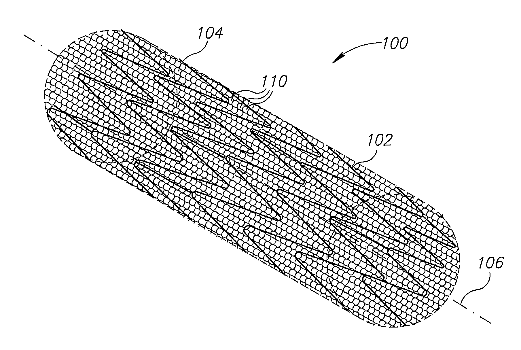
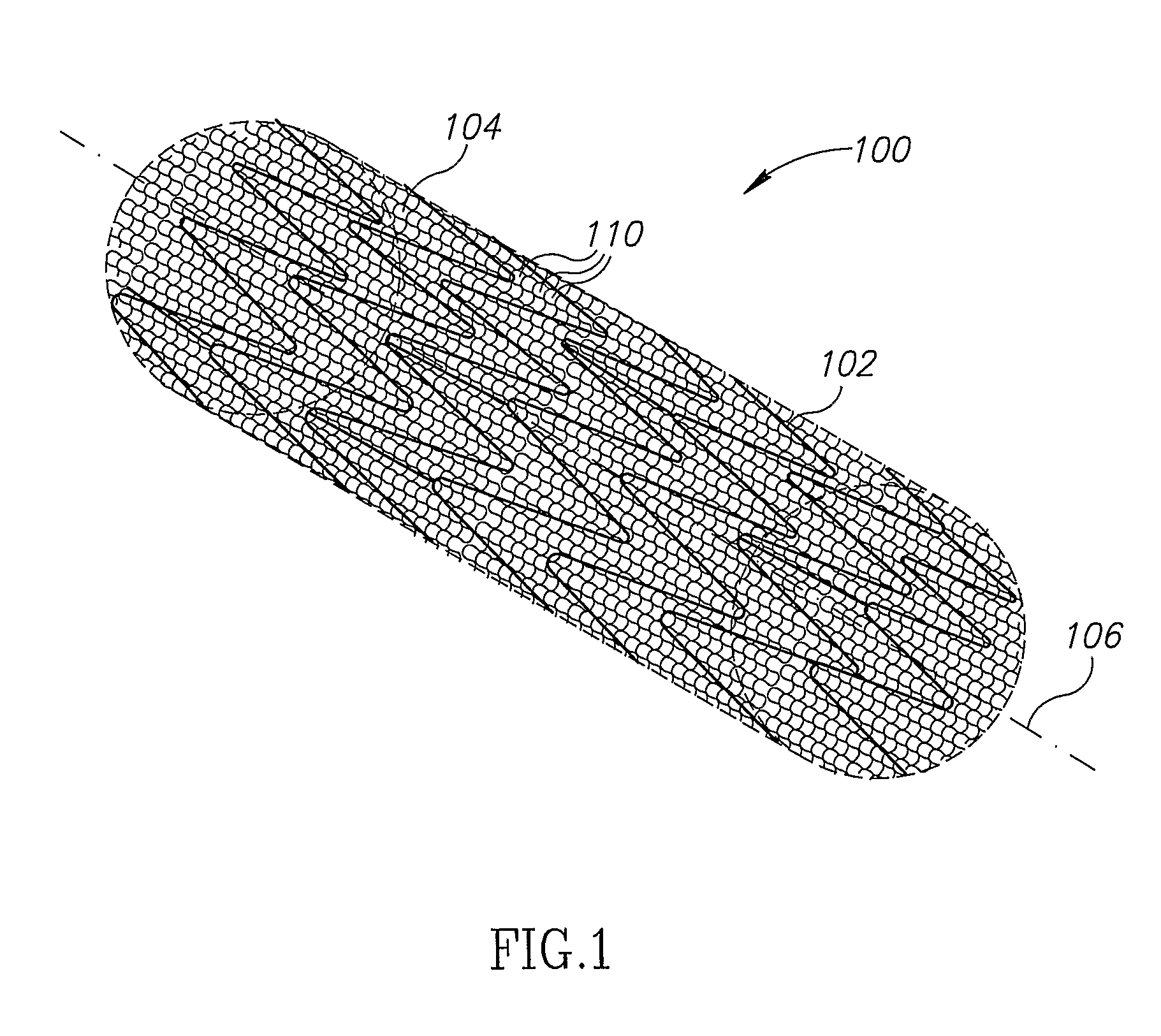
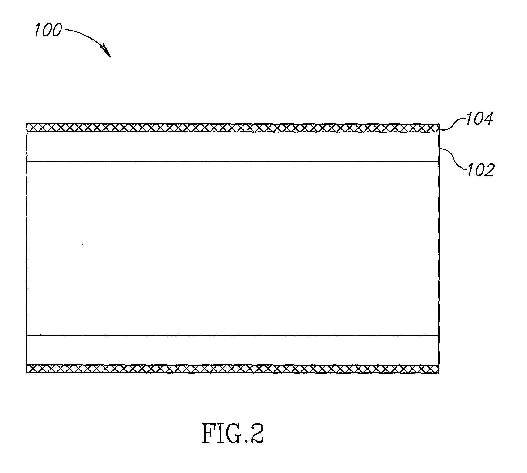
[0102]In an exemplary embodiment of the invention, an apparatus is provided which includes a porous structure and, optionally, an underlying support element, such as a stent (wherein underlying means the porous structure is between the support element and a lumen wall).

[0103]In some exemplary embodiments of th...


PUM

PropertyMeasurementUnit
Lengthaaaaaaaaaa
Fractionaaaaaaaaaa
Timeaaaaaaaaaa

Abstract

An enhanced stent apparatus, comprising: a support element, wherein the support element is constructed to be positioned in a body lumen; and, a porous structure, the porous structure located on a surface of the support element, and wherein the porous structure is comprised of at least one fiber under 30 microns in diameter, has a coverage area of less than 30% and is provided with apertures.

Description

RELATED APPLICATIONS[0001]This application claims the benefit under 119(e) of U.S. Provisional Applications No. 60 / 683,788, filed on May 24, 2005; No. 60 / 716,100, filed on Sep. 12, 2005; and, No. 60 / 742,460, filed Dec. 5, 2005, the disclosures of which are incorporated herein by reference.FIELD OF THE INVENTION[0002]Apparatuses and methods are provided for treatment and / or support via body lumens and / or other hollow organs.BACKGROUND OF THE INVENTION[0003]A stenosis is a stricture of a canal or duct. In the context of the vascular system a stenosis is a narrowing of the lumen of a blood vessel. A stenosis can severely restrict blood flow and promote thrombosis which can lead to myocardial infarction or stroke, for example. A common type of primary stenosis is caused by a buildup of atherosclerotic plaque.[0004]Several therapeutic methods have been developed to improve circulation and homeostasis in stenotic vessels including by-pass surgery and revascularization procedures. Revascul...

Claims


Application Information

Patent Timeline
IPC IPC(8): A61F2/06
CPCA61F2/07A61F2002/075A61F2002/077A61F2250/0023A61F2250/0039A61L2300/20A61F2230/0054A61F2230/0067A61F2/92A61F2/958A61L31/10A61F2/89A61F2220/005A61F2/90
Inventor HOLZER, ZEEV ASHERPAZ, OFIRBAR, ELICOHEN, ILANA
Owner INSPIRE M D LTD
Why Eureka
Try Eureka