

Flow reactor method and apparatus
- Summary
- Abstract
- Description
- Claims
- Application Information
AI Technical Summary
Benefits of technology
Problems solved by technology
Method used
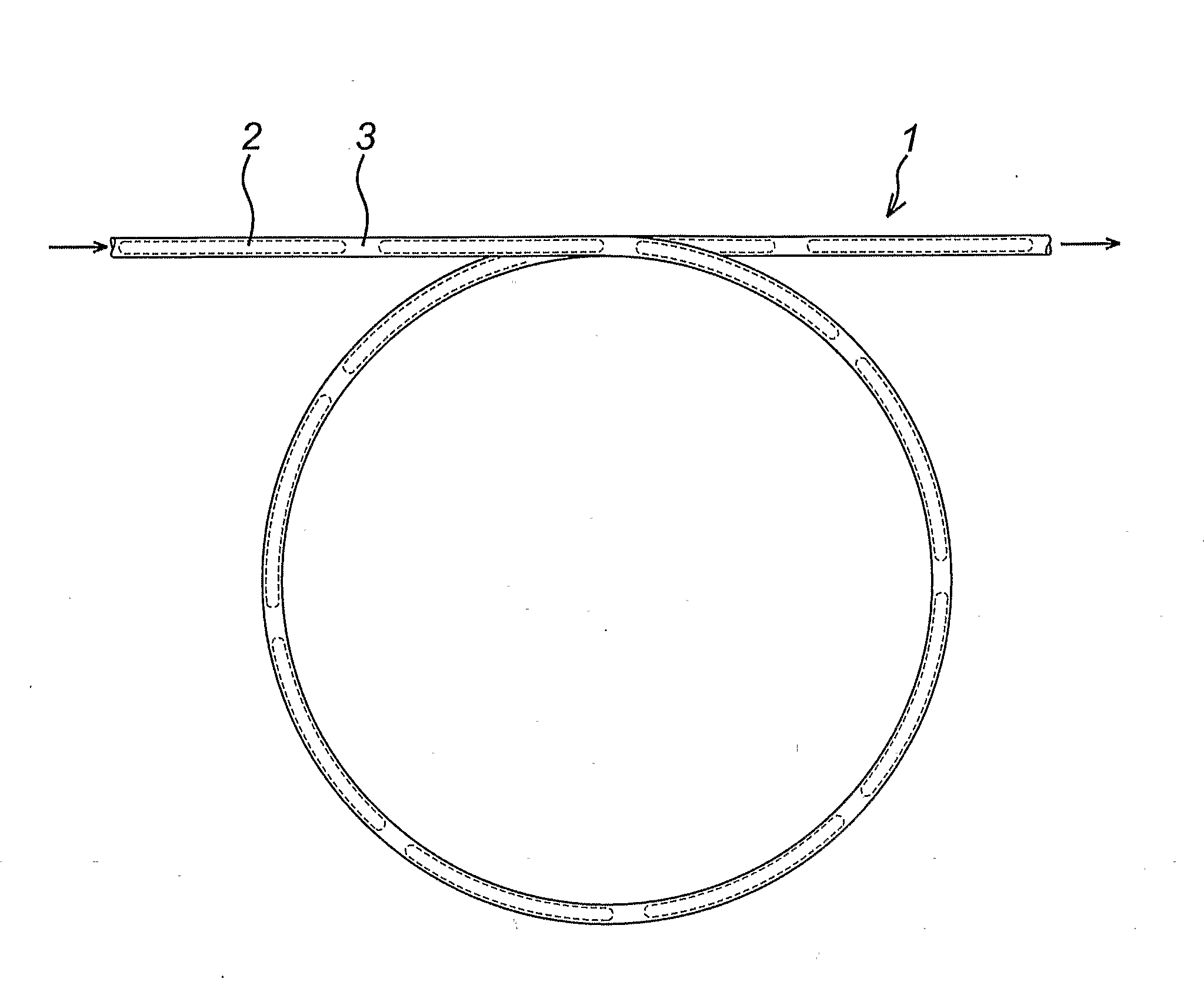
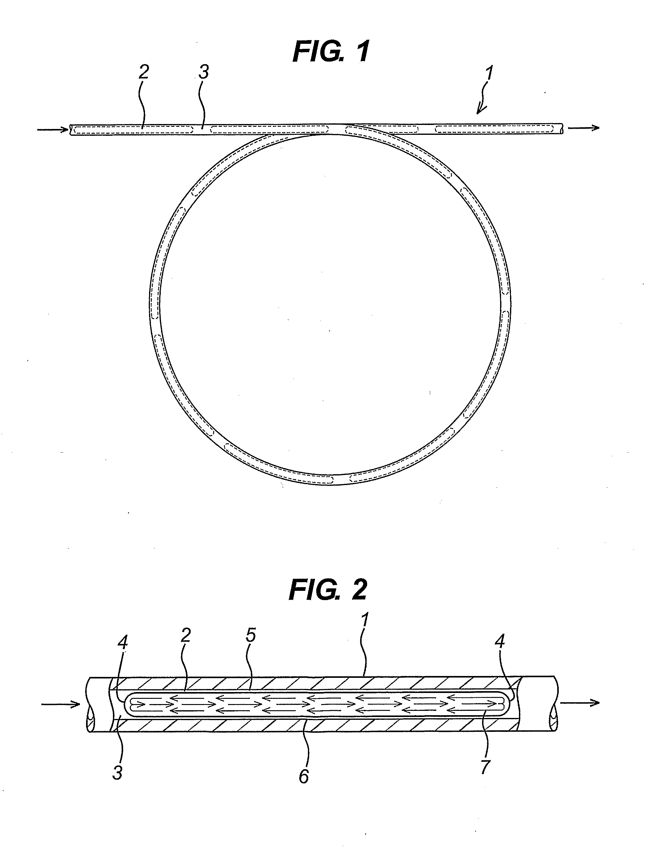
Image

Examples
example 1
Aromatic Substitution Reaction
[0072]
[0073]A 0.67M solution of fluoro nitro benzene in DMF was produced, and placed in reagent reservoir 1. A 0.67M solution of tryptamine in DMF was produced and placed in reagent reservoir 2.
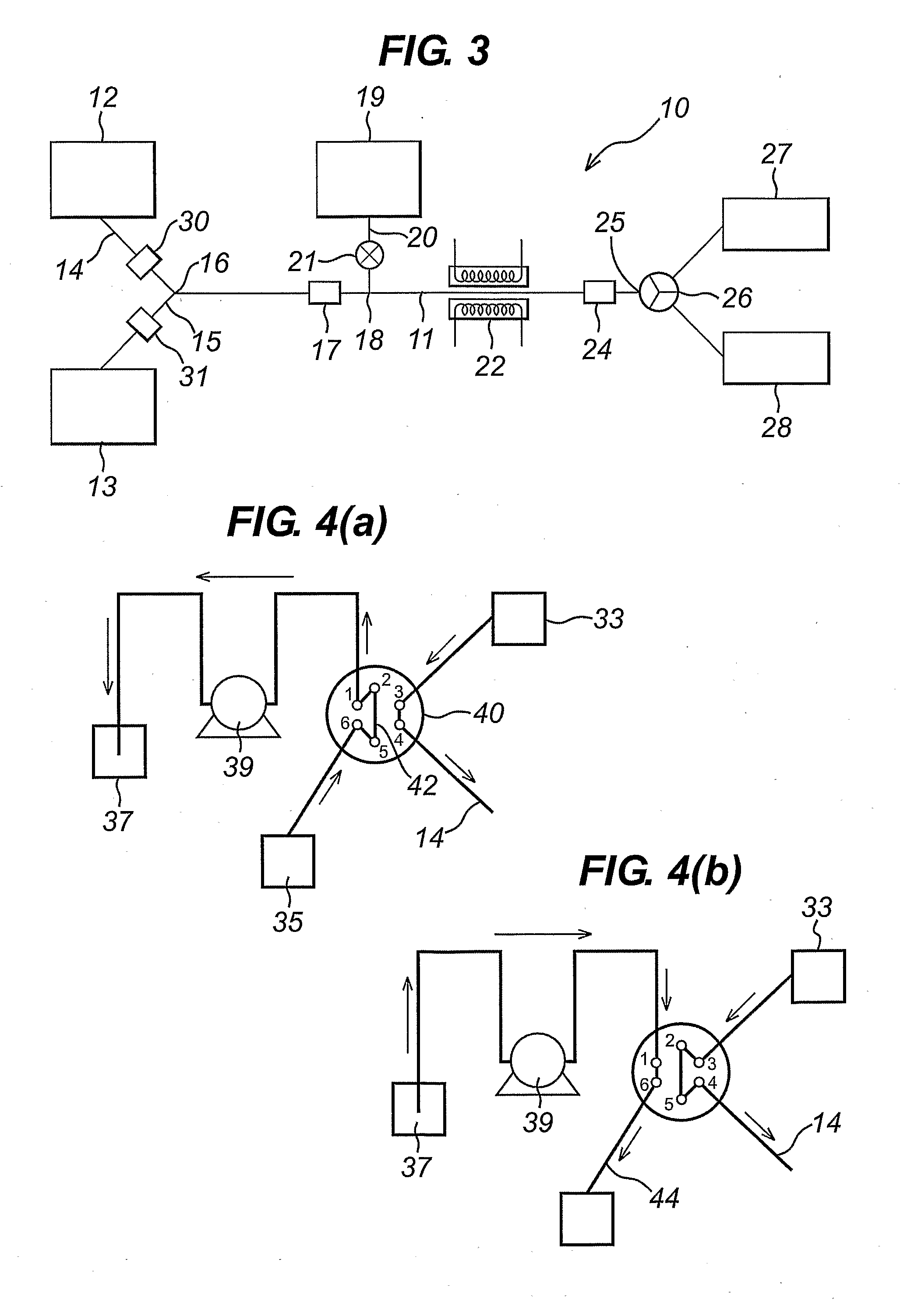
[0074]The apparatus comprised of 2 reagent injector systems, each containing a 2.7 ml injection loop as in FIG. 4a, and a reactor of volume 2.7 ml. All tubing in the system was PFA, of id 0.75 mm. Spacer solvent reservoirs contained PFMD. The reactor was of a configuration that allowed it to be heated electrically to a defined and controlled temperature.
[0075]Equal volumes of reagent 1 and reagent 2 were combined to form a reaction plug, sequential plugs were formed of increasing volume, reaction plugs were flowed through the reactor at a flow rate of 0.3 ml / min, and a temperature of 80° C., residence time of the reaction plug within the reactor was 9 mins. The reaction plug was collected at the outlet of the reactor, and quenched immediately into water. On compl...
example 2
Aromatic Substitution Using Microwave Activation
[0077]
[0078]A 0.4 M solution of 4-chloroquinoline in DMSO was produced, and placed in reagent reservoir 1. A 0.4 M solution of 4-morpholinoaniline in DMSO was produced and placed in reagent reservoir 2.
[0079]The apparatus comprised of 2 reagent injector systems, each containing a 2.7 ml injection loop as in FIG. 4a, and a reactor of volume 2.7 ml. All tubing in the system was PFA, of id 0.75 mm. Spacer solvent reservoirs contained PFMD. The reactor was of a configuration that allowed it to be activated by microwaves at a defined and controlled power, and the temperature moderated by the use of a flow of compressed air through the reactor cavity.
[0080]Equal volumes of reagent 1 and reagent 2 were combined to form a reaction plug, sequential plugs were formed of increasing volume, reaction plugs were flowed through the reactor at a flow rate of 0.54 ml / min, with a microwave power of 120 W. Residence time of the reaction plug within the r...
example 3
Sulphonamide Formation
[0081]
[0082]A 0.2 M solution of pipsyl chloride in dioxan was produced, and placed in reagent reservoir 1. A 0.24 M solution of tryptophan and sodium hydroxide in a 1.5:3.5 mixture of water:dioxan was produced and placed in reagent reservoir 2.
[0083]The apparatus comprised of 2 reagent injector systems, each containing 2×1 ml injection loops as in FIG. 5a, and a reactor of volume 6.7 ml. All tubing in the system was PFA, of id 0.75 mm. Spacer solvent reservoirs contained PFMD.
[0084]Equal volumes of reagent 1 and reagent 2 were combined to form a reaction plug, sequential plugs were formed of increasing volume, reaction plugs were flowed through the reactor at a flow rate of 1 ml / min, residence time of the reaction plug within the reactor was 6.7 mins. The reaction plug was collected at the outlet of the reactor, and quenched immediately into 0.5 M HCl. On completion of collecting the whole plug, the solution was extracted with DCM, and the extract evaporated to...
PUM
 Abstract
Description
Claims
Application Information