
System and method for converting software to a register transfer (RTL) design

a register transfer and software technology, applied in the field of hardware design, can solve the problems of increasing design size and complexity, time-consuming and expensive hardware design, and bottlenecks in design verification

Active Publication Date: 2009-06-04
EXAR CORP
View PDF11 Cites 38 Cited by
  • Summary
  • Abstract
  • Description
  • Claims
  • Application Information

AI Technical Summary

Benefits of technology

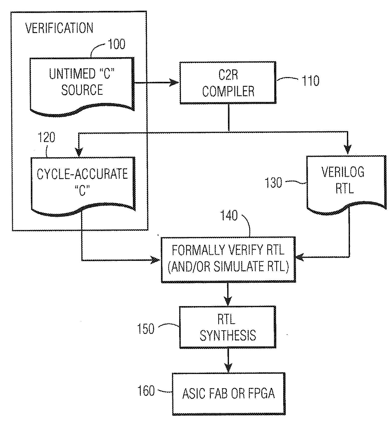
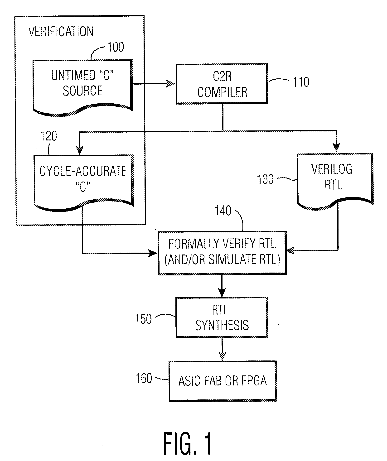
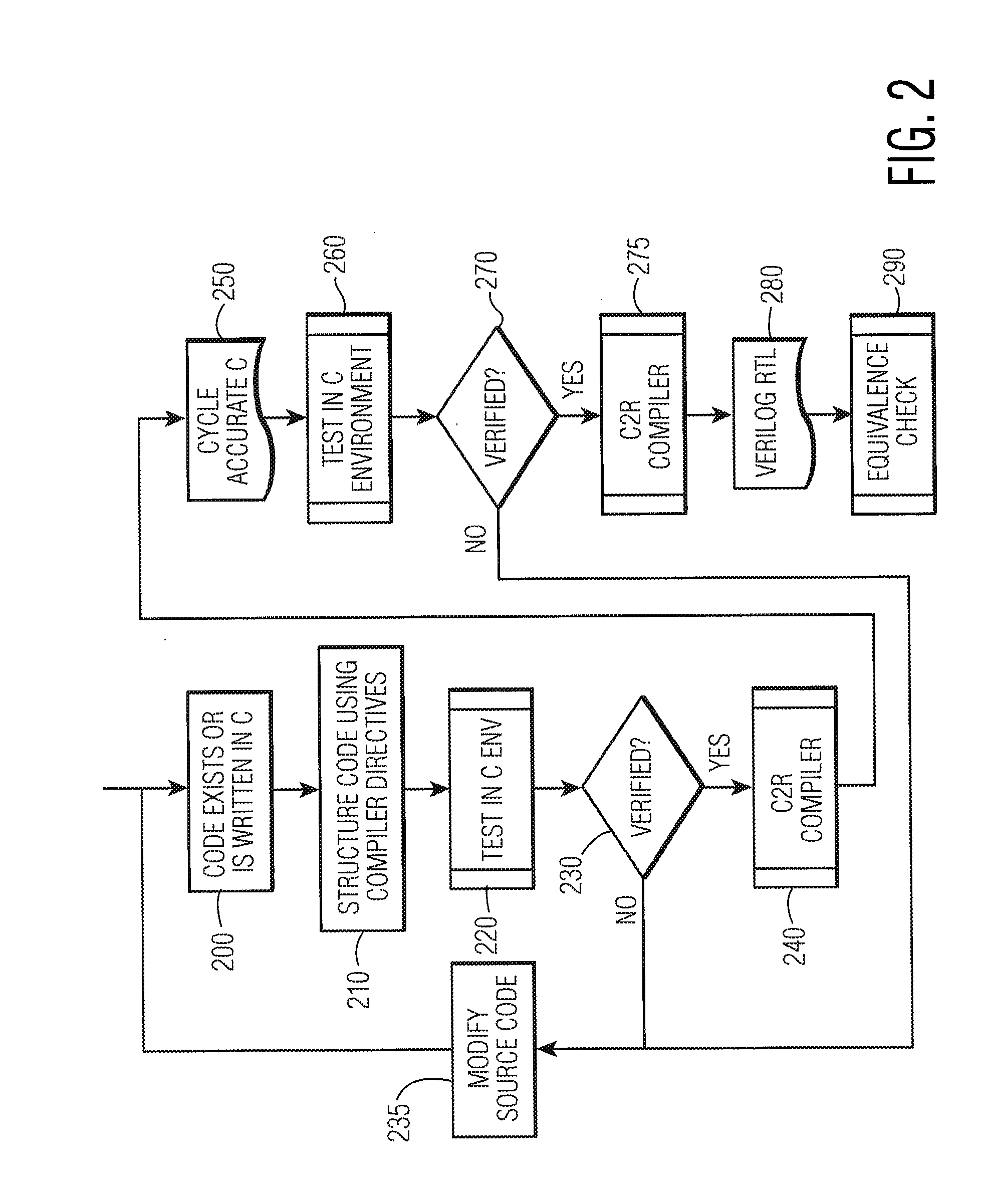
[0003]The invention is embodied in a method and system for converting program code that is not in a hardware description language (HDL) to hardware. The program code includes an algorithmic representation of one or more processes using variables. The method includes the program code being complied into an HDL synthesizable design such that each of said variables in the program code is categorized as using either a respective implicit memory or a respective custom memory. When a respective variable in the program code is categorized as using the respective implicit memory, a first type of accessor function for accessing the respective implicit memory is defined. Further, when the respective variable is categorized as using the respective custom memory, a second type of accessor function for accessing the respective custom memory is defined. The second type of access function is different from that of the first type. The hardware is generated by implementing the first and second accessor functions, as hardware, based on the HDL synthesizable design.

Problems solved by technology

The design of hardware (e.g., an Application-Specific Integrated Circuit (ASICs), or a Field Programmable Gate Array (FPGAs) among others) is time consuming and expensive.
Design verification is a bottleneck in current design cycles because design size and complexity have increased.
Using a conventional Register Transfer Level (RTL) design flow that relies on RTL simulation for verification may not be viable, because such an RTL simulation takes too long and is too costly.

Method used


Image

  • System and method for converting software to a register transfer (RTL) design
  • System and method for converting software to a register transfer (RTL) design
  • System and method for converting software to a register transfer (RTL) design

Examples


Embodiment Construction

[0031]Although the invention is illustrated and described herein with reference to specific embodiments, the invention is not intended to be limited to the details shown. Rather, various modifications may be made in the details within the scope and range of equivalents of the claims and without departing from the invention.

[0032]As used herein: Verilog® is a commonly used Hardware Description Language (HDL) which textually describes hardware at various levels of abstraction. The Register Transfer Level (RTL) is an intermediate level of abstraction that shows how data flows among registers and that may be used to synthesize a chip. Further, VHDL means VHSIC (Very-High-Speed Integrated Circuit) HDL, a design-entry language for FPGAs and ASICs in electronic design automation of digital circuits.

[0033]Conventional tools may be used to create hardware architecture source code by generating RTL to be verified in an RTL simulator. The verification in the RTL simulator is used because the s...


PUM


Abstract

A method for converting a C-type programming language program to a hardware design, where the said program is an algorithmic representation of one or more processes. The C-type programming language program is compiled into a hardware description language (HDL) synthesizable design. The compiler categorizes variables as using either implicit memory or custom memory. Different accessor functions are used depending on which type of memory is used. The programming language may use ANSI C and the HDL may be Verilog Register Transfer Level (RTL). The hardware device generated from the HDL synthesizable design may be an Application-Specific Integrated Circuit (ASIC) or a Field Programmable Gate Array (FPGA).

Description

FIELD OF THE DISCLOSURE[0001]This invention relates to hardware design. More specifically, this invention relates to hardware design using a software programming language.BACKGROUND OF THE INVENTION[0002]The design of hardware (e.g., an Application-Specific Integrated Circuit (ASICs), or a Field Programmable Gate Array (FPGAs) among others) is time consuming and expensive. Electronic Design Automation (EDA) tools strive to reduce verification time, design cycle time, and time to market of hardware. Design verification is a bottleneck in current design cycles because design size and complexity have increased. Using a conventional Register Transfer Level (RTL) design flow that relies on RTL simulation for verification may not be viable, because such an RTL simulation takes too long and is too costly.SUMMARY OF THE INVENTION[0003]The invention is embodied in a method and system for converting program code that is not in a hardware description language (HDL) to hardware. The program cod...

Claims


Application Information

Patent Timeline
Patent Type & Authority Applications(United States)
IPC IPC(8): G06F17/50
CPCG06F17/5045G06F30/30
Inventor SPACKMAN, CHADPORT, ADRIANLIPKE, LAWRENCE
Owner EXAR CORP
Learn More