Modulated transformer-coupled gate control signaling method and apparatus

a transformer-coupled gate and gate control technology, which is applied in the direction of process and machine control, pulse technique, instruments, etc., can solve the problems of limited pulse width range that can be generated by such circuits, complex control of such circuits, etc., and achieves zero net magnetization current, wide pulse width range, and robust control

Active Publication Date: 2009-06-11
CIRRUS LOGIC INC
View PDF19 Cites 87 Cited by
  • Summary
  • Abstract
  • Description
  • Claims
  • Application Information

AI Technical Summary

Benefits of technology

[0008]The above stated objective of providing a transformer-isolated gate drive circuit that requires few or no passive components to achieve a wide pulse width range with disable capability, is robust over environmental and operating conditions, provides substantially zero net magnetization current, and provides for use of smaller transformers, is achieved in a gate drive control circuit and method of operation. The circuit may be provided by a transformer and a set of integrated circuits, one of which provides the control signal on the primary side of the transformer, and the other of which provides the gate drive signal from the secondary side of the transformer.
[0009]On the primary side of the transformer, a control circuit generates a modulated control signal that is coupled to the primary winding of the transformer. A demodu

Problems solved by technology

However, such implementations typically require a relatively large number of passive components to complete the circuit, such as resistors, capacitors and/or snubbing/protection diodes to ensure that the gate of the transistor that is coupled to the transformer secondary is not damaged or improperly controlled, and that the transformer does not

Method used


Image

  • Modulated transformer-coupled gate control signaling method and apparatus
  • Modulated transformer-coupled gate control signaling method and apparatus
  • Modulated transformer-coupled gate control signaling method and apparatus

Examples


Embodiment Construction

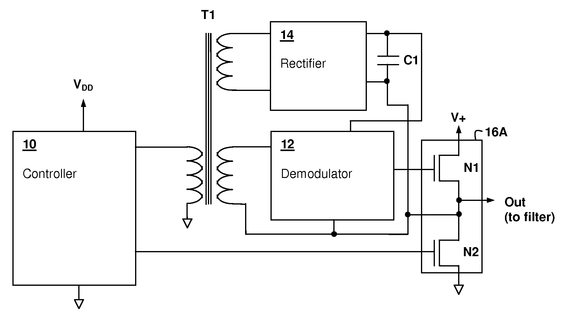
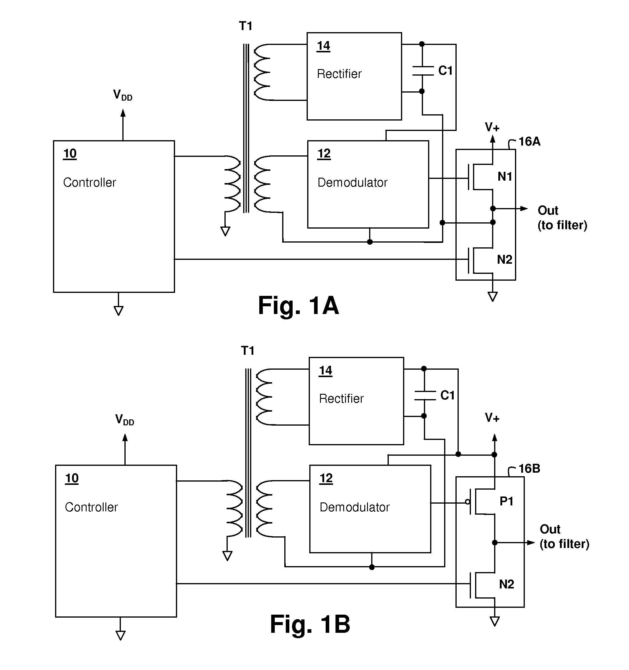
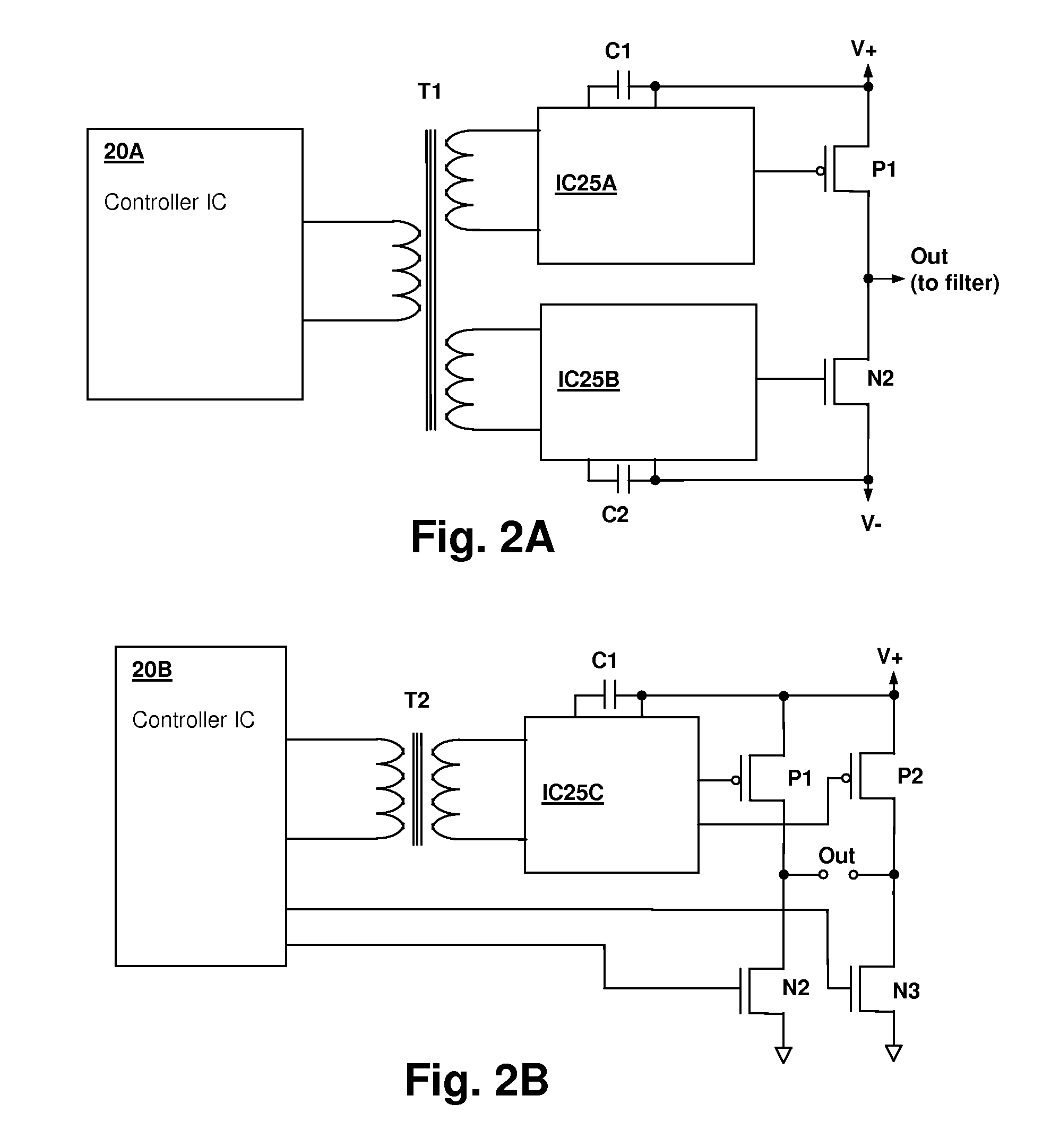
[0018]The present invention encompasses circuits and methods for providing drive signal(s) that control the gate(s) of one or more switching devices of a switching power stage. A transformer is used to isolate at least one gate drive circuit from a controller integrated circuit, and the control signal is modulated at a rate substantially higher than the switching control rate of the switching power stage, e.g., by a factor of 10, which permits transmission of additional or redundant information and robust operation with few additional components. Prior art transformer-isolated gate drive circuits typically passively couple the gate control signal(s) directly through the transformer and require additional components for shaping and snubbing the gate control signal. Variations in transformer characteristics from component to component and over environmental conditions, such as temperature, cause variation in the control signal(s). The present invention reduces the impact of such trans...


PUM


Abstract

A modulated transformer-coupled gate control signaling method and apparatus provides reduction of circuit complexity and robust design characteristics in switching power circuits having a transformer-coupled gate drive. A modulated control signal at a rate substantially higher than the switching circuit gate control rate is provided from the controller circuit to a demodulator via transformer coupling. Power for the demodulator can be obtained by rectifying the modulated control signal at the demodulator, or from another transformer winding. The modulation scheme is chosen to have a DC average value of zero, eliminating any magnetization current management requirements. The modulated control signal may carry redundant control information and/or may encode additional information to provide a more sophisticated gate drive control, such as oversampled gate control information.

Description

BACKGROUND OF THE INVENTION[0001]1. Field of the Invention[0002]The present invention relates generally to power switching circuits having a transformer-coupled gate control, and more specifically, to a gate drive control circuit using a control signal modulated to a rate higher than the switching rate.[0003]2. Background of the Invention[0004]Transformer coupling of gate drive control is used in power switching circuits in which the transformer gate control signal either requires complete DC isolation from the switching control circuit, or in which the gate control voltage for at least one of the switching transistors is sufficiently high with respect to the controller integrated circuit operating voltage that transformer coupling of the gate control signal relaxes the voltage-handling requirements for the control circuit drive output(s). The transformer can also be used to step up a lower voltage switching signal, so that the higher voltage required to drive the gate of at least o...

Claims


Application Information

Patent Timeline
IPC IPC(8): H02M3/335
CPCH03K17/691H02M1/08
Inventor MELANSON, JOHN L.
Owner CIRRUS LOGIC INC
Why Eureka
Try Eureka