Methods of generating energetic particles using nanotubes and articles thereof
a technology of energy particles and nanotubes, applied in nuclear engineering, nuclear reactors, greenhouse gas reduction, etc., can solve problems such as substantial change of the current state of power distribution
- Summary
- Abstract
- Description
- Claims
- Application Information
AI Technical Summary
Benefits of technology
Problems solved by technology
Method used
Image
Examples
example 1
Production of Energetic Particles Using Treated Carbon Nanotubes
[0062]a) Production of Carbon Nanotube Material
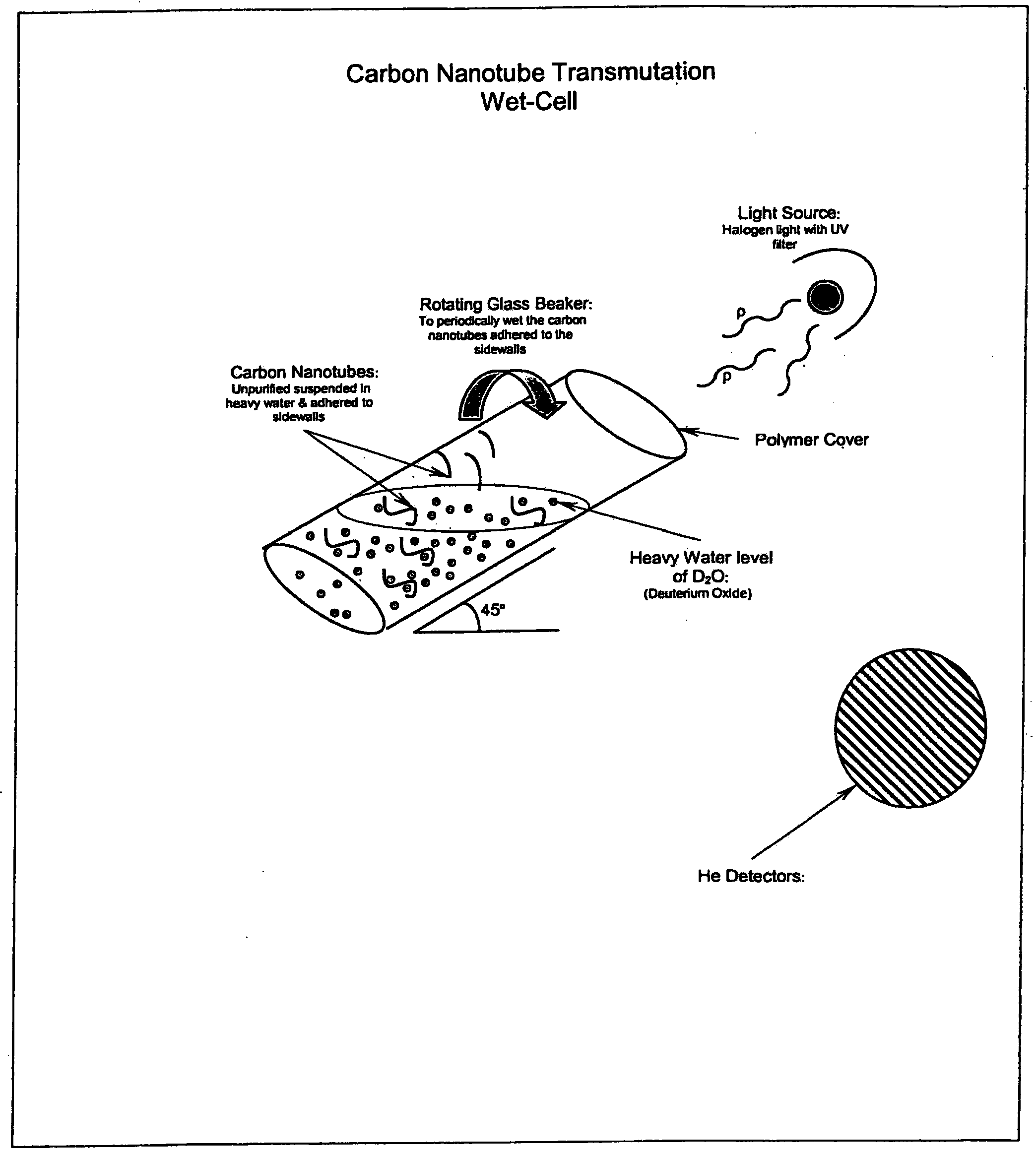
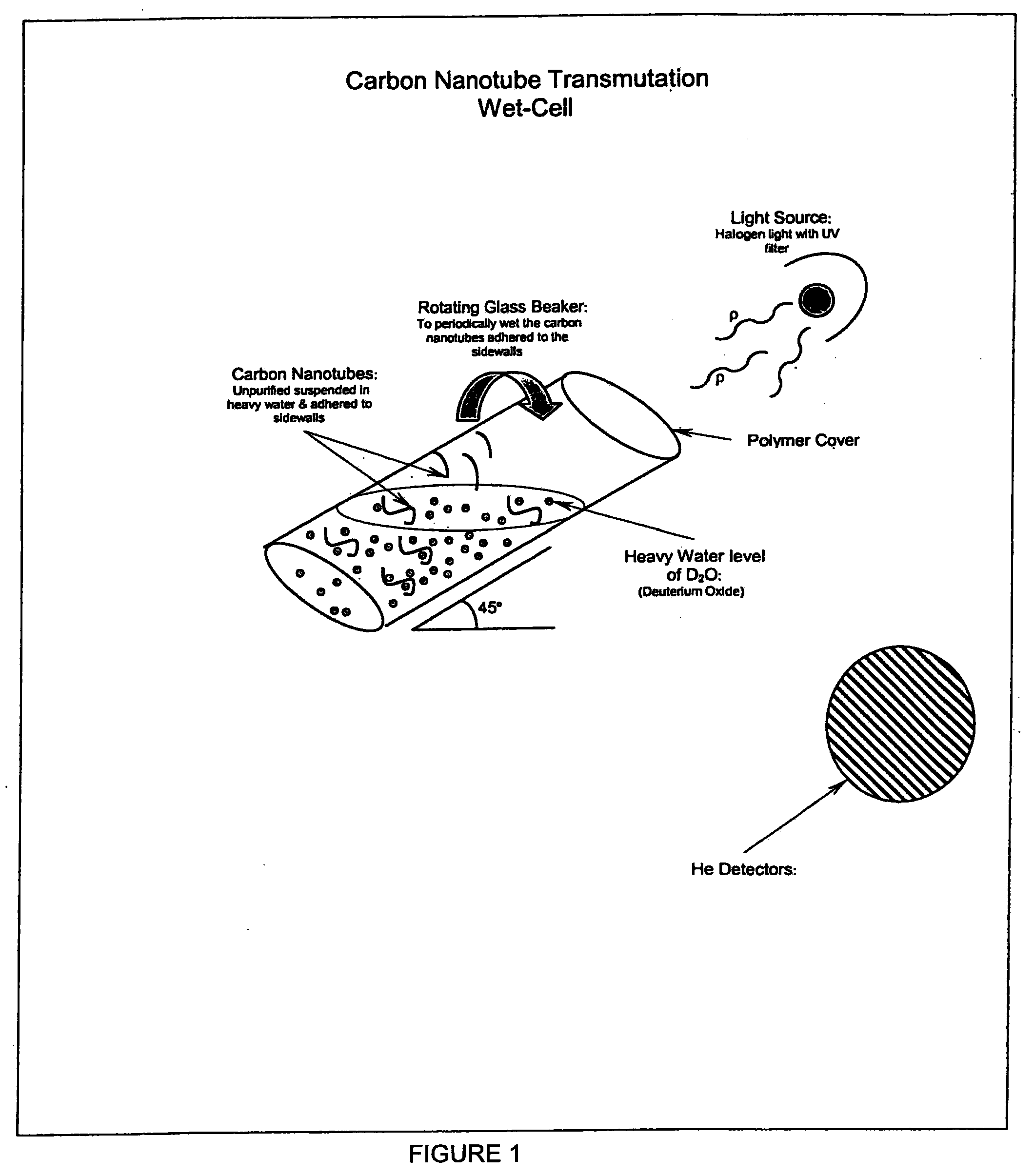
[0063]5 g of carbon nanotubes were mixed with 250 ml of reagent grade nitric acid at room temperature. The carbon nanotubes were multi-walled, with diameters ranging from 10 nm to 50 nm and lengths ranging from 100 nm to 100 um. After 20 minutes, the carbon nanotubes were removed from the nitric acid and washed with water three times. The carbon nanotubes were dried in an oven set above room temperature to remove water. From that batch, 100 mg of the carbon nanotubes were combined with 3540 ml of 99.9% pure D2O in a 50 ml glass beaker (Sample A). The D2O was taken from a new 250 gram sample that was purchased from Sigma Aldrich (Part number 151882-250G, Batch number 08410KC).
[0064]b) Measurements on Carbon Nanotube Material
[0065]Various energetic particles emitted from Sample A were measured in the following manner:
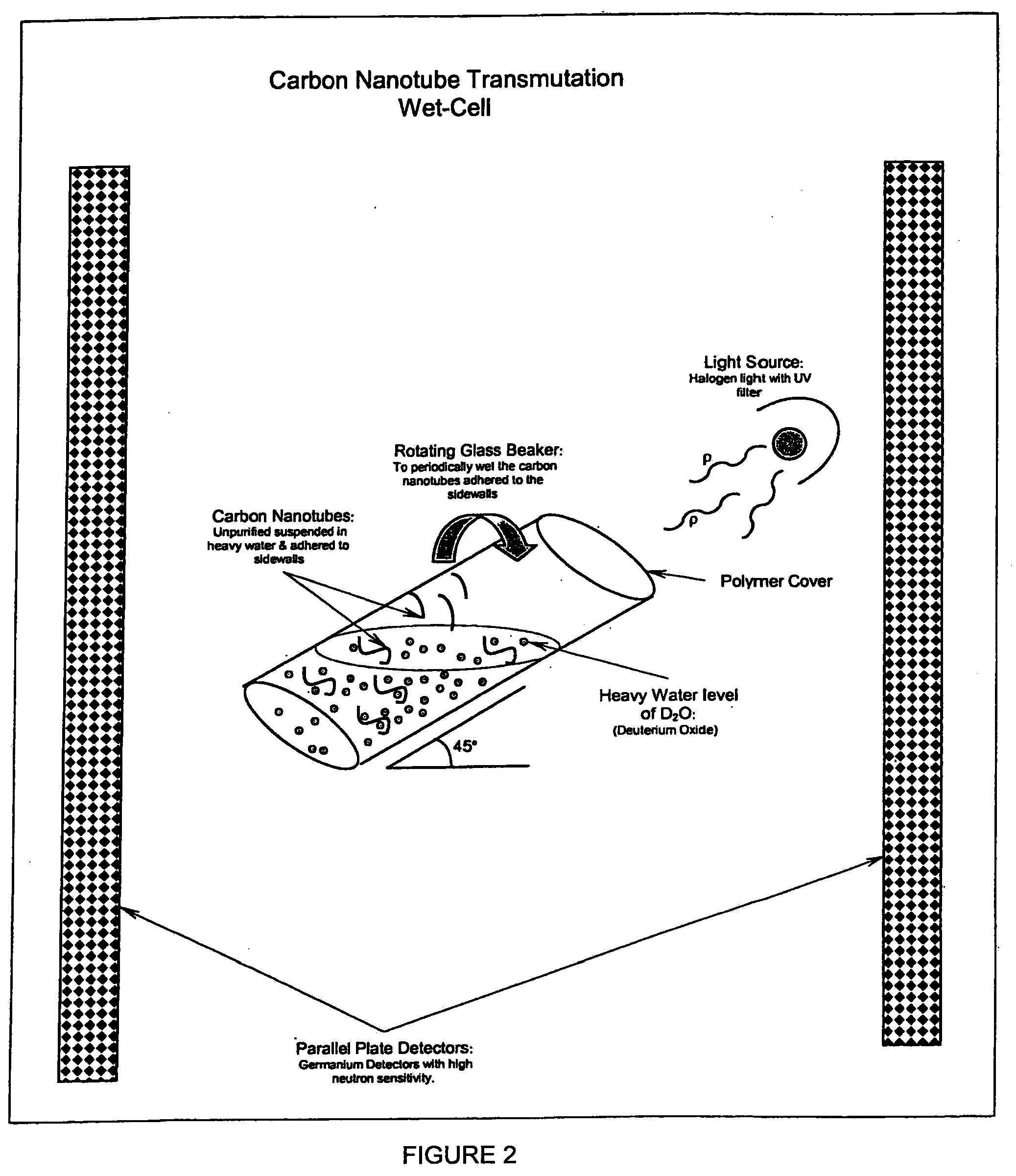
[0066]Sample A was covered with clear plastic wrap to minim...
example 2
Production of Energetic Particles Using Untreated Carbon Nanotubes
[0070]a) Production of Carbon Nanotube Material
[0071]This example was substantially similar to Ex. 1, with the exception that untreated multi-walled carbon nanotubes were used in this example. The carbon nanotubes had diameters ranging from 10 nm to 50 nm and lengths ranging from 100 nm to 100 um. About 100 mg of the carbon nanotubes were combined with 35-40 ml of 99.9% pure D2O in a 50 ml glass beaker.
[0072]b) Measurements on Carbon Nanotube Material
[0073]Energetic particles emitted from the sample made according to this invention were measured in the following manner:
[0074]As in Example 1, the sample according to this example was covered with clear plastic wrap to minimize evaporation of the D20 and water absorption into the hydroscopic D20. It was then placed in a rotatable sample holder, which was held at a 45 degree angle relative to the floor and rotated at about 1 rpm during measurement so as to keep the surfac...
example 3
Production of Energetic Particles Via Transmutation in a Liquid Phase—without an Electrolysis Electrode
[0078]In this example the nanotubes were commercially pure carbon nanotubes obtained from NanoTechLabs (NanoTechLabs Inc., 409 W. Maple St., Yadkinville, N.C. 27055). They had a length of approximately 3 mm, with a 6 member ring structure and were straight in orientation. The carbon nanotubes were substantially defect free and were not treated prior to use in the device.
[0079]A bundle of aligned carbon nanotubes containing approximately 1,000 individual nanotube was connected to stainless steel electrodes at each end of the bundle. The carbon nanotube electrode system was measured to have approximately 200Ω of resistance. One nanotube electrode was connected through a capacitor to ground and to a 19.5 μl resistor connected to the high voltage supply. See FIG. 3. The other nanotube electrode was connected through a 30 ns rise time transistor to ground. The gate on the transistor was...
PUM
 Abstract
Description
Claims
Application Information
 - R&D
- Intellectual Property
- Life Sciences
- Materials
- Tech Scout
- Unparalleled Data Quality
- Higher Quality Content
- 60% Fewer Hallucinations
Browse by: Latest US Patents, China's latest patents, Technical Efficacy Thesaurus, Application Domain, Technology Topic, Popular Technical Reports.
© 2025 PatSnap. All rights reserved.Legal|Privacy policy|Modern Slavery Act Transparency Statement|Sitemap|About US| Contact US: help@patsnap.com


