
Plastic surfaces and apparatuses for reduced adsorption of solutes and methods of preparing the same

a technology applied in the field of plastic surfaces and apparatuses for reducing adsorption of solutes and methods of preparing the same, can solve the problems of high cost and labor intensity of photolithography and etching techniques, cost and time savings, and require clean-room conditions, so as to achieve less likely to adsorb and more hydrophilic

Inactive Publication Date: 2009-06-11
SCIEX
View PDF9 Cites 42 Cited by
  • Summary
  • Abstract
  • Description
  • Claims
  • Application Information

AI Technical Summary

Benefits of technology

[0055]According to one embodiment, a method is disclosed for treating plastic surfaces with a first gas comprising fluorine gas and a second gas comprising oxygen gas, water vapor, or a combination of oxygen gas and water vapor, the treatment making the surfaces less likely to adsorb hydrophobic solutes. In some embodiments, the method comprises treating the plastic surface with a mixture of fluorine gas and an inert gas for a period of time, and then flushing the surface with air, the overall process making the surface more hydrophilic. The plastic surface can be pretreated by being placed under vacuum and / or by being exposed to air or an inert gas environment. In some embodiments, the plastic surface comprises the interior surface of a microfluidic chip or one or more surfaces of a microtiter plate, a pipette, a micropipette tip, a tube, a syringe, a storage vessel, or a length of tubing.

Problems solved by technology

Photolithography and etching techniques, however, are costly and labor intensive, require clean-room conditions, and pose several disadvantages from a materials standpoint.
The increasing complexity of microfluidic devices has created a demand to use such devices in a rapidly growing number of applications.
The miniaturization of drug testing techniques promised by microfluidics potentially represents great cost and time savings for the drug industry by reducing the amount of drug candidate and other reagents needed for testing, by reducing waste, and by reducing the number of separate handling steps involved in a particular assay.
Miniaturization does, however, come with its own set of technical issues.
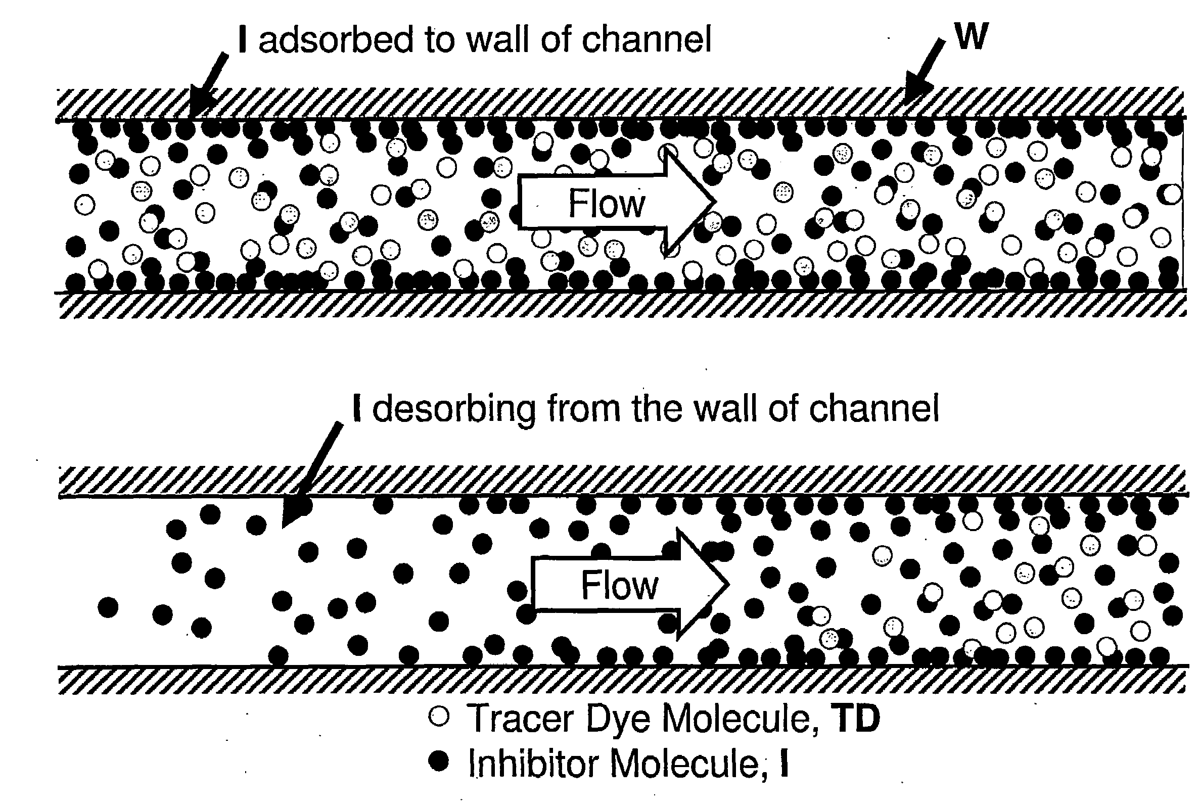
Thus, adsorption of test molecules and other reagents to device walls can have more serious consequences on sample concentrations than it can in conventional, non-miniaturized devices.
All in all, these issues mean that the adsorption of solute molecules in microfluidic systems and other miniaturized devices can be an obstacle to the use of those systems and devices when concentration control is a consideration.
The problem of compound adsorption to surfaces potentially affects devices other than microfluidic channels.

Method used


Image

  • Plastic surfaces and apparatuses for reduced adsorption of solutes and methods of preparing the same
  • Plastic surfaces and apparatuses for reduced adsorption of solutes and methods of preparing the same
  • Plastic surfaces and apparatuses for reduced adsorption of solutes and methods of preparing the same

Examples


example 1

Dependence of Surface Hydrophilicity on Fluorination Time

[0198]A flat piece of polycarbonate (formed from a CALIBRE™ 200 series resin, Dow Chemicals, Wilmington, Del., USA) was treated according to the method of the following steps:[0199](1) the surface was flushed with air for about 1 minute;[0200](2) the surface was placed in a vacuum for about 1 minute;[0201](3) the surface was flushed with a fluorine gas mixture containing 5% fluorine and 95% neon for a period of time;[0202](4) the surface was flushed with air for about 1 minute; and[0203](5) the surface was placed in a vacuum for about 1 minute.

[0204]FIG. 5 shows the contact angle between water and the treated polycarbonate for polycarbonate samples treated with the fluorine gas mixture for different periods of time. As can be seen in FIG. 5 at time 0, the contact angle of untreated polycarbonate is about 55, indicating that it is hydrophobic, but not as hydrophobic as, for example, TEFLON®. After approximately 2½ minutes, the ...

example 2

IC50 Determination Using a Non-Treated SPA

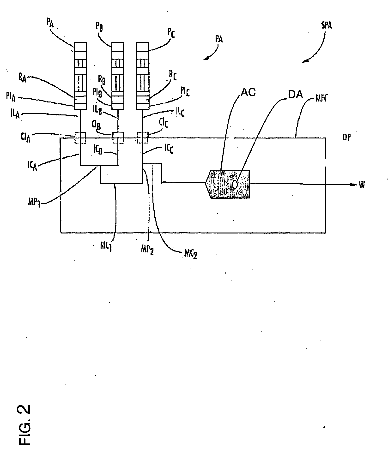
[0205]FIG. 6 shows the results of a typical experiment to measure IC50 using a sample processing apparatus SPA as depicted in FIG. 2. The pumps contained the following:[0206]PA: inhibitor+tracer dye (ALEXA FLUOR 700™, Invitrogen, Carlsbad, Calif., USA)+enzyme substrate+buffer[0207]PB: enzyme substrate+buffer[0208]PC: coupling enzymes+target enzyme+resazurin (also from Invitrogen)

The tracer dye is added to the solution containing the inhibitor such that measurement of the concentration of ALEXA FLUOR 700™ in the solution reports the concentration of the inhibitor, so long as the inhibitor does not adsorb to the walls of the microfluidic chip. If adsorption occurs, the concentration of the inhibitor will vary in expected ways, as discussed below. Resazurin is a non-fluorescent precursor that is converted to highly fluorescent resorufin by the action of the target enzyme and the coupling enzymes. The pump flow rates varied as follows:

1300 to 13...

example 3

IC50 Determination Using a Treated SPA

[0212]FIG. 9 shows the data from an experiment identical to that described above in Example 2, with the exception that the experiment whose data is reported in FIG. 9 was performed in a microfluidic chip that had been treated by the method of the presently disclosed subject matter. The upper graph of FIG. 9 is the data from FIG. 6 redrawn for ease of comparison. The lower graph is data from the experiment in treated microfluidic chip MFC. Most notably, enzyme plot EP in the lower graph rises to full activity more quickly than in the upper graph, indicating that the inhibitor concentration decreases more quickly, as expected if adsorption has been reduced in the experiment for the lower graph.

[0213]FIG. 10 presents the data from the lower graph of FIG. 9 transformed to concentration versus enzyme activity to determine the inhibitor's IC50. The x-axis is the concentration of the inhibitor, as reported by the tracer dye, which is tracer plot TP in ...


PUM


Abstract

A method of treating a plastic surface with fluorine gas to decrease adsorption of hydrophobic solute molecules to the surface is provided. The method can include treating a surface with a first gas comprising fluorine gas and a second gas comprising oxygen gas, water vapor, or both oxygen gas and water vapor. Plastics treated using the method provide useful drug discovery and biochemical tools for the testing, handling, and storage of solutions containing low concentrations of hydrophobic solutes. Microfluidic devices containing treated plastic interior surfaces and methods of using such devices to make concentration-dependent measurements are also described.

Description

CROSS-REFERENCE TO RELATED APPLICATIONS[0001]This application claims the benefit of U.S. Patent Application Ser. No. 60 / 707,288, filed Aug. 11, 2005, the disclosure of which is incorporated herein by reference in its entirety. The disclosures of the following U.S. Provisional Applications, commonly owned and simultaneously filed Aug. 11, 2005, are all incorporated by reference in their entirety: U.S. Provisional Application entitled MICROFLUIDIC APPARATUS AND METHOD FOR SAMPLE PREPARATION AND ANALYSIS, U.S. Provisional Application 60 / 707,373 (Attorney Docket No. 447 / 2 / 1); U.S. Provisional Application entitled APPARATUS AND METHOD FOR HANDLING FLUIDS AT NANO-SCALE RATES, U.S. Provisional Application No. 60 / 707,421 (Attorney Docket No. 447 / 99 / 212); U.S. Provisional Application entitled MICROFLUIDIC BASED APPARATUS AND METHOD FOR THERMAL REGULATION AND NOISE REDUCTION, U.S. Provisional Application No. 60 / 707,330 (Attorney Docket No. 447 / 99 / 2 / 3); U.S. Provisional Application entitled MI...

Claims


Application Information

Patent Timeline
IPC IPC(8): B01L3/00B05D3/00
CPCB01L3/00C08J7/126C08J7/12B01L3/5027
Inventor PETTIGREW, KENNETH I.KUNG, PANG-JEN CRAIGSTECHER, JOSHUA T.SMITH, GREGORY FENTONCRENSHAW, HUGH C.
Owner SCIEX
Learn More