
Olefin polymerization reactor, polyolefin production system, and polyolefin production process

a technology of polymerization reactor and production system, applied in chemical/physical/physical-chemical stationary reactors, chemical/physical/physical-chemical processes, chemistry apparatus and processes, etc., can solve the problems of large reactor height, large amount of energy required, and complicated construction, and achieve excellent structural uniformity

Active Publication Date: 2009-06-11
SUMITOMO CHEM CO LTD
View PDF41 Cites 42 Cited by
  • Summary
  • Abstract
  • Description
  • Claims
  • Application Information

AI Technical Summary

Benefits of technology

[0009]It is therefore an object of the present invention to provide an olefin polymerization reactor which has a simple construction, yet can substantially reduce the residence time distribution. Another object of the invention is to provide a polyolefin production system which likewise has a simple construction yet is able to substantially reduce the residence time distribution. A further object of the invention is to provide a polyolefin production process which uses such an olefin polymerization reactor or polyolefin production system.
[0026]The present invention provides an arrangement which, although simple, enables a narrow residence time distribution to be achieved As a result, when an olefin polymer is continuously produced, it is possible to produce polymer having an excellent structural uniformity, in addition to which polymer replacement in the reactor with changes in the production conditions is easy.

Problems solved by technology

This results in a more complicated construction, in addition to which a large amount of energy is required for agitate the particles.
In the process of U.S. Pat. No. 5,235,009, wherein a plurality of fluidized beds are connected in series in the vertical direction, the need to provide a freeboard at each stage may result in an enormous reactor height.
With circulating fluidized bed reactors like those described in Japanese Translation of PCT Application No. 2002-520426 and European Patent Laid-open Publication No. 1484343, each polyolefin particle repeatedly circulates within the reactor, making it difficult to remove polyolefin particles from the unit in a plug flow manner.

Method used


Image

  • Olefin polymerization reactor, polyolefin production system, and polyolefin production process
  • Olefin polymerization reactor, polyolefin production system, and polyolefin production process
  • Olefin polymerization reactor, polyolefin production system, and polyolefin production process

Examples


example 1

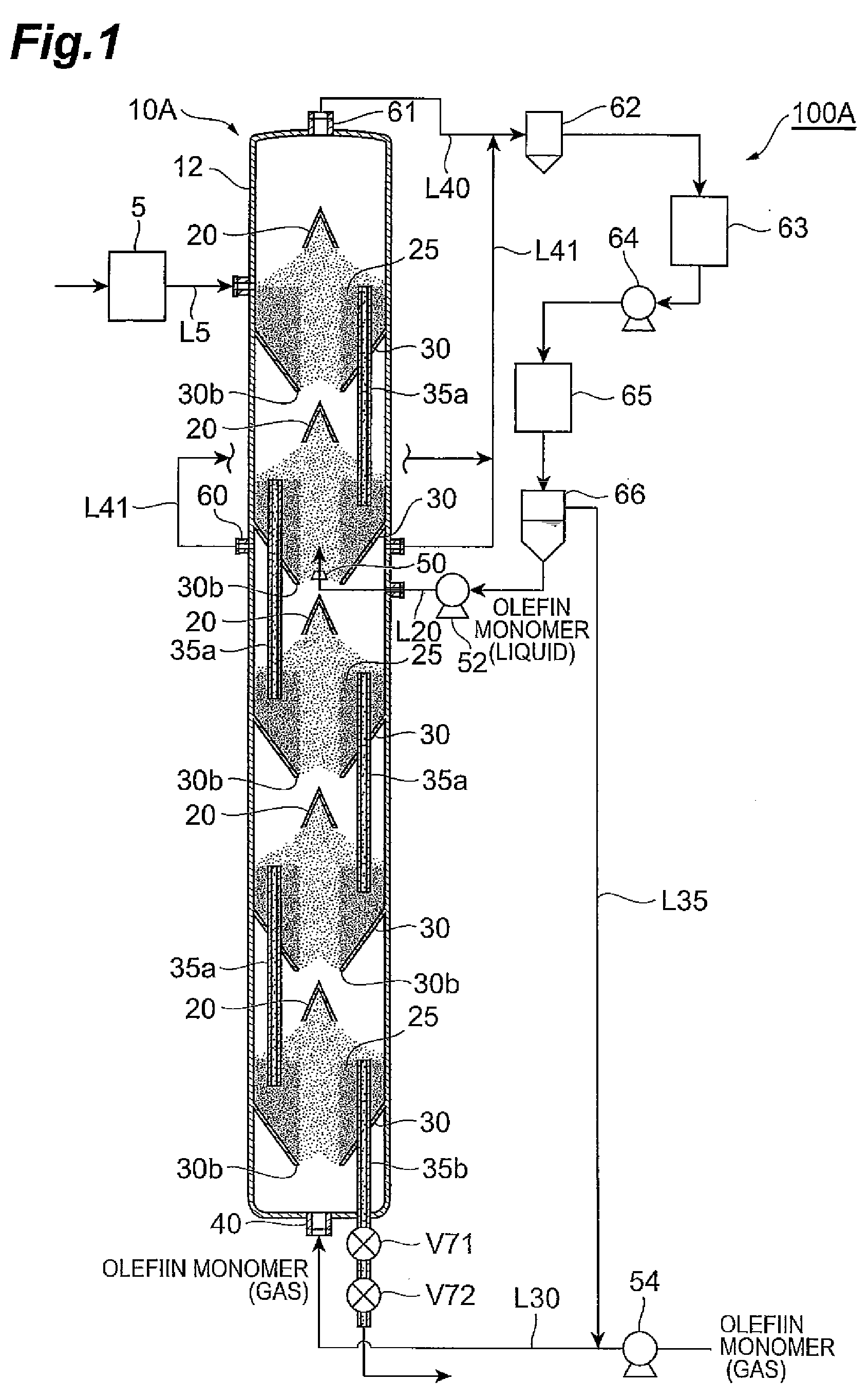
[0148]A cylindrical cold model reactor made of transparent polyvinyl chloride and capable of forming two spouted beds inside the cylinder was furnished to investigate the residence time distribution in an olefin polymerization reactor according to the present invention. This unit had two tubular baffles of inverted conical shape with a gas inlet orifice therein, each of which was paired with a conical deflector, disposed vertically and coaxially within the cylinder.

[0149]The cylindrical cold model reactor had an inside diameter dB of 500 mm, and the gas inlet orifice at the bottom end of each tubular baffle had a diameter dA of 100 mm. Accordingly, in the present example, the ratio dA / dB between the gas inlet orifice diameter dA and the cylinder inside diameter dB was 0.2.

[0150]The angle of inclination between the inside surfaces of the tubular baffles of inverted conical shape and the horizontal and the angle of inclination between the outside surfaces of the deflectors and the hor...

examples 2 to 9

[0155]Examples 2 to 9 below were carried out to investigate the relationship between the stability of a spouted bed formed in a reaction zone and the shape of the tubular baffle.

example 2

[0156]A cylindrical cold model reactor made of transparent polyvinyl chloride and capable of forming a single spouted bed inside the cylinder was furnished for use. This reactor had, disposed within the cylinder, a single tubular baffle with an inverted conical shape having a gas inlet orifice and, paired with the baffle, a single deflector with a conical shape.

[0157]The cylindrical cold model unit had an inside diameter dB of 500 mm, and the gas inlet orifice at the bottom end of the tubular baffle had a diameter dA of 100 mm. Accordingly, in the present example, the ratio dA / dB between the gas inlet orifice diameter dA and the cylinder inside diameter dB was 0.2.

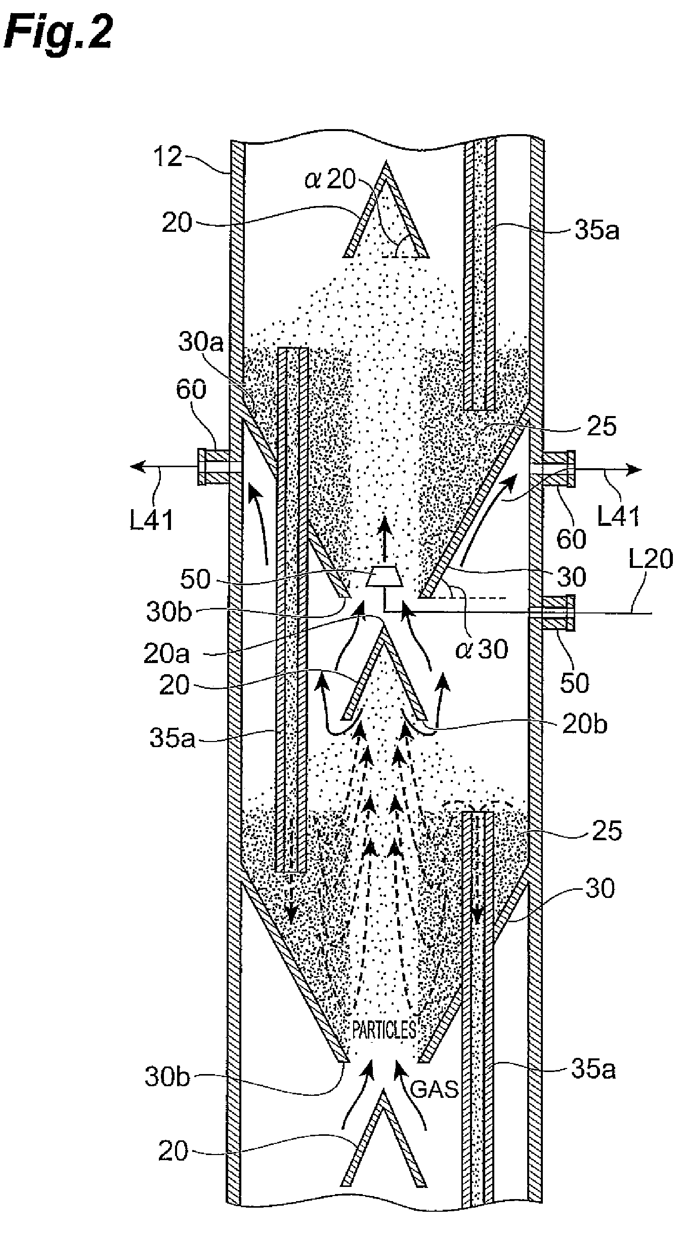
[0158]The angle of inclination between the inside surface of the tubular baffle having an inverted conical shape and the horizontal and the angle of inclination between the outside surface of the deflector and the horizontal were each 65°. The conical deflector had an inside diameter at the bottom end of 300 mm, and was ho...


PUM


Abstract

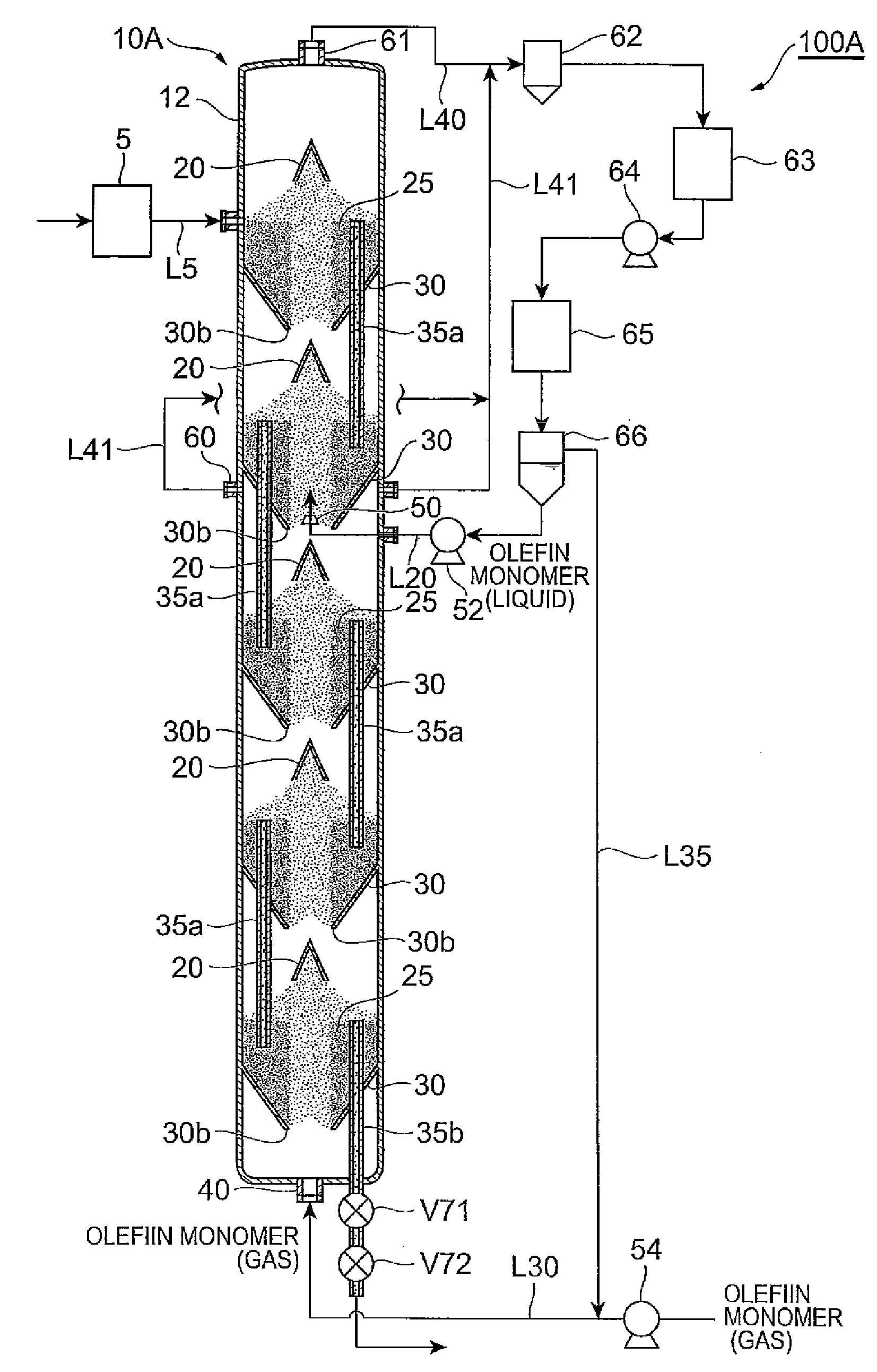
An olefin polymerization reactor of the present invention includes a cylinder which extends vertically, and a decreasing diameter member which is formed on the cylinder, has an inside diameter that decreases progressively downward and has a gas inlet orifice at a bottom end thereof. A spouted bed is formed inside a reaction zone enclosed by an inside surface of the decreasing diameter member and an inside surface of the cylinder above the decreasing diameter member.

Description

BACKGROUND OF THE INVENTION[0001]1. Field of the Invention[0002]The present invention relates to an olefin polymerization reactor which uses a spouted bed, to a polyolefin production system which uses a spouted bed, and to a process for producing polyolefins such as polyethylene and polypropylene using such a reactor or system.[0003]2. Related Background Art[0004]Olefin polymerization reactors which polymerize, within a vessel and in the presence of a catalyst, an olefin monomer fed in as a gas or liquid to form granular polyolefin particles are known to the art. However, in a single vessel, the polyolefin particles approach a completely mixed state, as a result of which there is a tendency for a short path characterized by the discharge of particles that have not grown to a sufficient size to arise or for particles that have grown too large to accumulate within the vessel.[0005]In such cases, the formed particles have a poor structural uniformity. Other problems that tend to arise ...

Claims


Application Information

Patent Timeline
IPC IPC(8): B01J19/00C08F210/00C08F2/01
CPCC08F10/00C08F210/06B01J8/245B01J2208/00283B01J2208/00274B01J2208/0007B01J2208/00292C08F2/34C08F2/001C08F210/16C08F2500/17
Inventor SATO, HIDEKIOGAWA, HIROYUKI
Owner SUMITOMO CHEM CO LTD
Learn More