White light emitting device and producing method thereof
a technology of white light and emitting device, which is applied in the manufacture of electric discharge tube/lamp, discharge tube luminescnet screen, electrode system, etc., can solve the problems of not being applied to an apparatus which requires a wider chromatic range, such as a display panel, and the chromatic range is too narrow to cover a wide chromatic range, so as to improve chromatic range, simplify the structure, and reduce the cost
- Summary
- Abstract
- Description
- Claims
- Application Information
AI Technical Summary
Benefits of technology
Problems solved by technology
Method used
Image

Examples
first embodiment
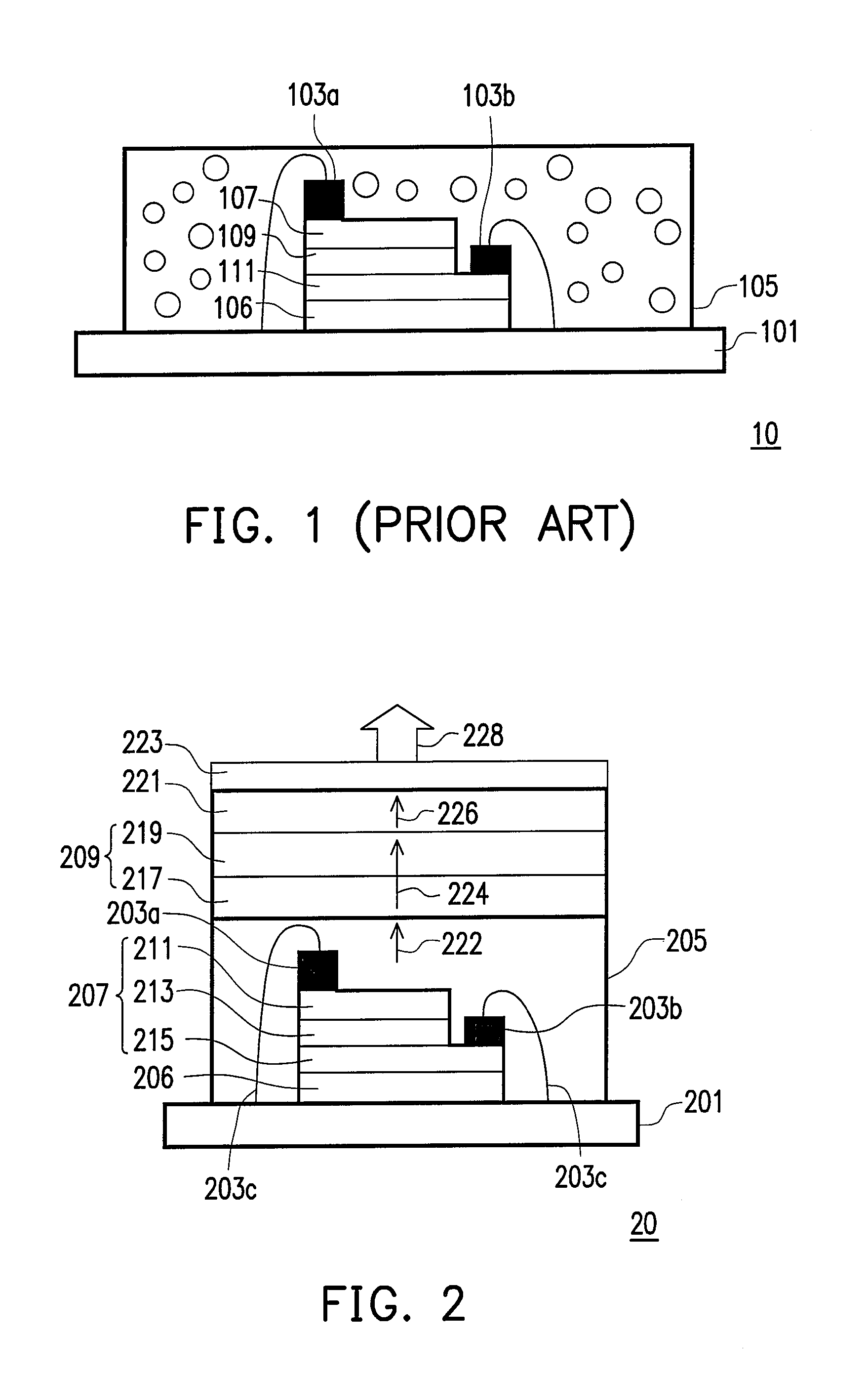
[0022]FIG. 2 is a schematic cross-sectional view of a white-light emitting device according to the present invention. Referring to FIG. 2, the embodiment provides a white-light emitting device 20, which comprises a circuit substrate 201, a substrate 206 disposed on the circuit substrate 201, a first electrode 203a, a second electrode 203b, a short wavelength light source 207, a protective layer 205, a first structure 209, and a second structure 221.
[0023]The short wavelength light source 207 is disposed on the substrate 206 and electrically connected to the circuit substrate 201 by the first electrode 203a, the second electrode 203b, and conductive lines 203c. The short wavelength light source 207 is electrified to generate a first light 222, which is, for example, blue light. The protective layer 205 covers the short wavelength light source 207. According to the embodiment, the protective layer 205 and the circuit substrate 201 form a hermetic chamber, in which the short wavelength...
third embodiment
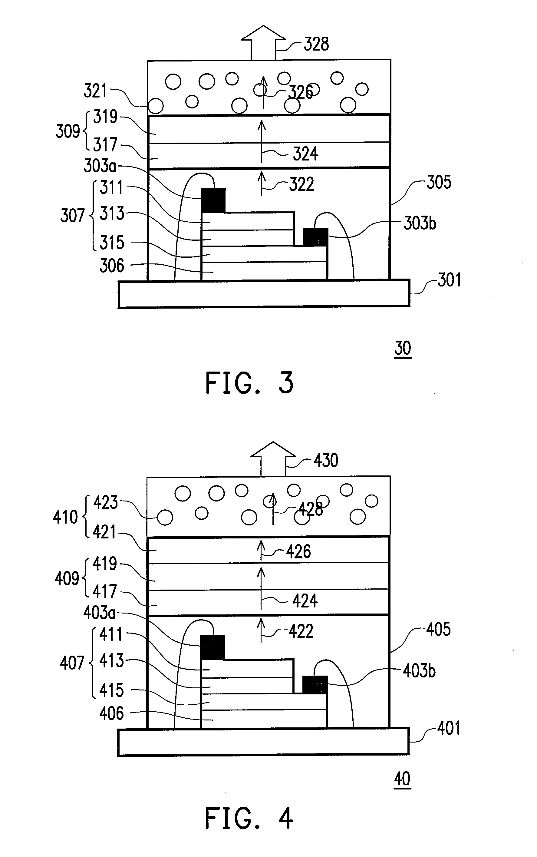
[0037]What distinguishes the third embodiment from the previous embodiments is that the second structure 410 comprises, for example, a second quantum well structure 421 and a fluorescent layer structure 423 for generating a third light 426 and a fourth light 428. In this embodiment, the second quantum well structure 421 absorbs a portion of the first light 422, a portion of the second light 424, or simultaneously absorbs a portion of the first light 422 and a portion of the second light 424 to generate a portion of the third light 426. In addition, the fluorescent layer structure 423 absorbs a portion of the first light 422, a portion of the second light 424, and a portion of the third light 426; or merely absorbs a portion of the first light 422 and a portion of the second light 424; or merely absorbs a portion of the first light 422 to generate a fourth light 428. The white-light emitting device 40 then generates a white light 430 by mixing the second light 424, the third light 42...
fourth embodiment
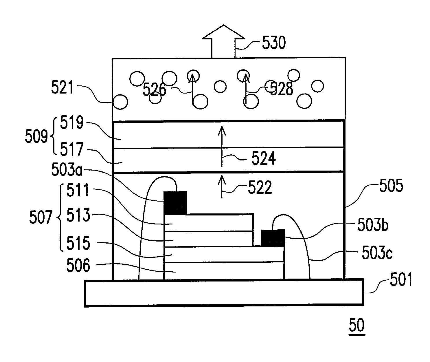
[0038]FIG. 5 is a schematic cross-sectional view of a white-light emitting device 50 according to the present invention. Referring to FIG. 5, the embodiment provides a white-light emitting device 50, which comprises a circuit substrate 501, a substrate 506, a first electrode 503a, a second electrode 503b, a short wavelength light source 507, a protective layer 505, a first structure 509, and a second structure 521. Similarly, the first structure 509 comprises a first quantum well layer 517 and a transmission layer 519.
[0039]What distinguishes the fourth embodiment from the previous embodiments is that the second structure 521 is, for example, a fluorescent layer structure, which simultaneously generates a third light 526 and a fourth light 528. The second structure 521 absorbs a portion of a first light 522 or a portion of a second light 524, or simultaneously absorbs a portion of the first light 522 and a portion of the second light 524 to generate the third light 526 and the fourt...
PUM
 Abstract
Description
Claims
Application Information
 - R&D
- Intellectual Property
- Life Sciences
- Materials
- Tech Scout
- Unparalleled Data Quality
- Higher Quality Content
- 60% Fewer Hallucinations
Browse by: Latest US Patents, China's latest patents, Technical Efficacy Thesaurus, Application Domain, Technology Topic, Popular Technical Reports.
© 2025 PatSnap. All rights reserved.Legal|Privacy policy|Modern Slavery Act Transparency Statement|Sitemap|About US| Contact US: help@patsnap.com