Viewing angle controlling system, and image display device using the same

a control system and angle technology, applied in the direction of instruments, polarising elements, optics, etc., can solve the problems of confidential information leakage, information leakage out, device has such a risk, etc., and achieve the effect of viewing angle control, thin, light and inexpensiv

Inactive Publication Date: 2009-06-18
NITTO DENKO CORP
View PDF15 Cites 67 Cited by
  • Summary
  • Abstract
  • Description
  • Claims
  • Application Information

AI Technical Summary

Benefits of technology

[0022]Furthermore, as shown in FIG. 11, it is preferred that in the case where the display panel is a liquid crystal display 300 having a polarizer 1 over at least one principle surface of a liquid crystal cell, the polarizer functions as the first polarizer 1 of the viewing angle controlling system 100. According to this embodiment, the number of members can be reduced, and the reduction can contribute to the matter that the liquid crystal display is made thin, light, and inexpensive.
[0023]Further, as shown in FIG. 14, another preferred embodiment of the image display device of the invention includes a selfluminous-type display panel 500, and the viewing angle controlling system 100 is arranged on the vi

Problems solved by technology

However, the device has such a risk that its screen is peeped by others on a platform of a station, or in a public facility such as a coffee shop or on a train so that privacy is invaded, confidential information leaks out, or the like.
Further, in the same case as in an automatic teller machine (ATM) or others, there would be a risk that a personal identification number or the like is peeped when the machine is operated, so that information leaks out.
In the meantime, in the case of displays adapted for cars, such as a car navigation system, there is caused a problem that light emitted upwards from the display is projected on the front window, in particular, in

Method used


Image

  • Viewing angle controlling system, and image display device using the same
  • Viewing angle controlling system, and image display device using the same
  • Viewing angle controlling system, and image display device using the same

Examples


production example 1

[0146]To 100 parts by weight of a monofunctional thermotropic cyanobiphenyl based nematic liquid crystal monomer having a polymerizable group at a terminal thereof, 25 parts by weight of a polymeric liquid crystal (manufactured by Kurogane Kasei Co., Ltd.; copolymerization ratio n=35) represented by a chemical formula illustrated below as an additive for an improvement in vertical alignment property, 400 parts by weight of 4-methyl-2-pentanone (MIBK) as a solvent, and 5 parts by weight of a polymerization initiator (IRGACURE 907, manufactured by Ciba Geigy Corporation) were added, mixed and dissolved to prepare a liquid crystal composition solution. In addition, a dye solution was prepare in the way that 1.5 parts by weight of a polyazo based dye having an absorption peak at a wavelength of 458 nm, 0.8 parts by weight of a polyazo based dye having an absorption peak at a wavelength of 542 nm and 1 part by weight of a polyazo based dye having an absorption peak at a wavelength of 621...

production example 2

[0147]The same process as in Production Example 1 was carried out except that the direction of the direct electric field applied at the time of the radiation of ultraviolet rays was inclined at an angle of 20° from the normal line direction of the film plane, so as to produce a polarizer having an absorption axis in a direction other than the directions perpendicular to and parallel to the normal line of the film plane. In the same manner as in Production Example 1, the TAC film was caused to adhere onto both surfaces of the polarizer. In this way, a “polarizing plate B” was produced.

example 1

Formation of a Viewing Angle Controlling System

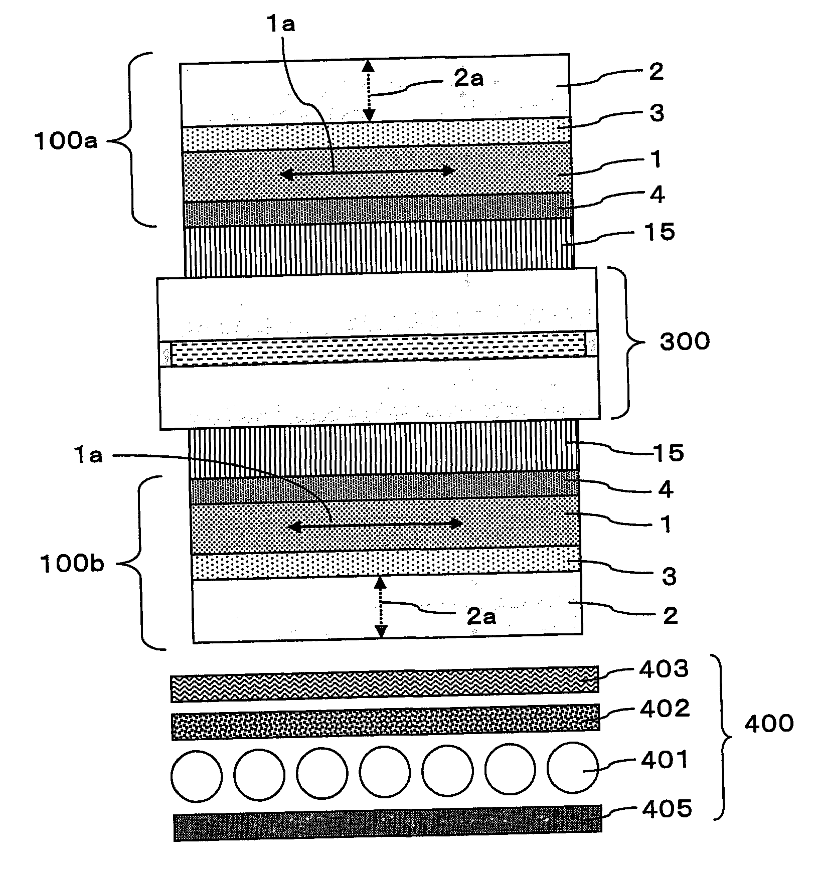
[0148]An acryl-based pressure-sensitive adhesive agent was used to cause a iodine-based polarizer (SIG 1463 DU, manufactured by Nitto Denko Corporation, hereinafter referred to as “polarizing plate C”) having an absorption axis in the film plane to adhere onto one of the principle surfaces of the polarizing plate A produced in Production Example 1. In this way, a “viewing angle controlling system D” was formed.

(Formation of an Image Display Device)

[0149]The viewing-side polarizing plate of a VA mode liquid crystal display (AQUOS, manufactured by Sharp Corporation) was peeled off therefrom in which a viewing-side polarizing plate and a light-source-side polarizing plate are arranged in a cross Nicol state, the light-source-side polarizing plate has a retardation film having biaxial property (nx>ny>nz), and the viewing-side polarizing plate has no optical compensation film, and instead of this viewing-side polarizing plate, the viewing an...


PUM


Abstract

There are provided a viewing angle controlling system which can be used in a display device for which peep-prevention and viewing-angle-control are required, and makes it possible to control the viewing angle of a display, and an image display device using the same.
The viewing angle controlling system includes: a first polarizer and a second polarizer which are each in the form of a film comprising an absorption dichroic material. The first polarizer has an absorption axis in its film plane, and the second polarizer has an absorption axis in the range of angle from 0 to 45° to the normal line of its film plane.

Description

BACKGROUND OF THE INVENTION[0001]1. Field of the Invention[0002]The present invention relates to a viewing angle controlling system, and an image display device using the same.[0003]2. Description of the Related Art[0004]Image display devices, such as liquid crystal displays (LCD), plasma display devices (PDP) and EL display devices (ELD), are used for various purposes and scenes since the display devices have advantageous characteristics that: the display devices may be thin and light; the power consumption thereof is low; the screen thereof can be made large and the like. In particular, LCDs or ELDs are widely used as display devices of personally-used information devices, such as notebook computers or cellular phones. In some cases, such an information device is used to handle data including personal data, trade secrets or the like. However, the device has such a risk that its screen is peeped by others on a platform of a station, or in a public facility such as a coffee shop or ...

Claims


Application Information

Patent Timeline
IPC IPC(8): G02F1/1335G02B5/30
CPCG02B27/28G02F2001/133531G02F1/133528G02F1/133531
Inventor UMEMOTO, SEIJI
Owner NITTO DENKO CORP
Why Eureka
Try Eureka