
Alkaline storage cell

a technology negative electrodes, which is applied in the direction of cell components, non-aqueous electrolyte accumulator electrodes, electrical apparatuses, etc., can solve the problems of low corrosion resistance of alkaline electrolyte, short cycle life, and poor discharge characteristics of negative electrodes, so as to improve the cycle life characteristic improve the corrosion resistance and oxidation resistance, and increase the operation voltage of alkaline storage cells

Inactive Publication Date: 2009-06-18
SANYO ELECTRIC CO LTD
View PDF10 Cites 9 Cited by
  • Summary
  • Abstract
  • Description
  • Claims
  • Application Information

AI Technical Summary

Benefits of technology

[0010]It is an object of the present invention to provide an alkaline storage cell of which rare earth-Mg—Ni hydrogen storage alloy has a stable crystal structure, and which has improved cycle-life and discharge characteristics.
[0012]In the alkaline storage cell according to one aspect of the present invention, a large amount of Al forms a solid solution in the parent phase of the rare earth-Mg—Ni hydrogen storage alloy. This is because the rare earth-Mg—Ni hydrogen storage alloy contains Sm as its essential element, and the subscript α indicating the ratio of the content of the element represented by A is 0.40 or greater. The formation of the solid solution with a large amount of Al makes the crystal structure of the rare earth-Mg—Ni hydrogen storage alloy stable, and improves the corrosion resistance and oxidation resistance. As a result, the cycle-life characteristic of the alkaline storage cell is improved.
[0013]Further, the subscript α being 0.40 or greater raises the hydrogen equilibrium pressure of the rare earth-Mg—Ni hydrogen storage alloy. This increases the operation voltage of the alkaline storage cell, thus improving the discharge characteristic.

Problems solved by technology

While this type of hydrogen storage alloy stores a large amount of hydrogen, the alloy has problems that it does not easily release the hydrogen stored, and that the corrosion resistance to the alkaline electrolyte is low.
Due to these problems, the alkaline storage cell using the rare earth-Mg—Ni hydrogen storage alloy for the negative electrode has a poor discharge characteristic and a short cycle life.
However, even the use of the rare earth-Mg—Ni hydrogen storage alloy disclosed in the Document 1 does not sufficiently improve the characteristics of the alkaline storage cell.

Method used

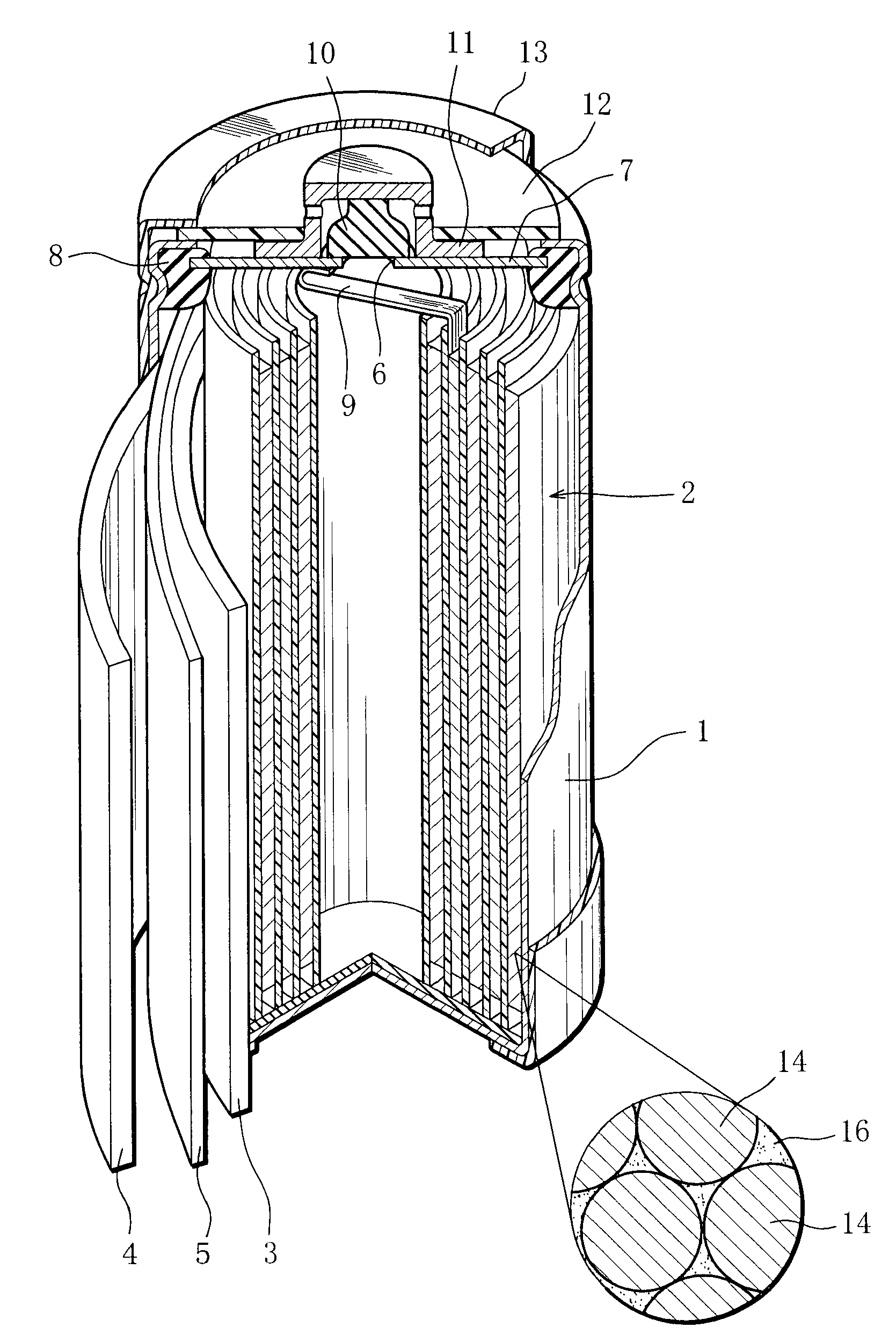
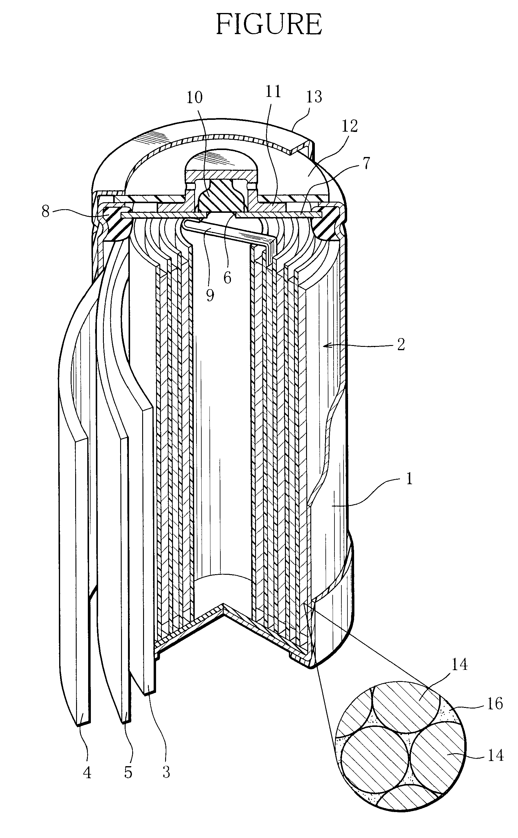

Image

  • Alkaline storage cell
  • Alkaline storage cell

Examples


examples

1. Preparation of Negative Electrode

[0043]Metal materials were measured out to have the compositions of Examples 1 to 7 and Comparative Examples 1 to 6 and mixed, and the mixtures were melted in a high-frequency melting furnace, yielding a plurality of ingots. Those ingots were heated in an argon atmosphere at the temperature of 1000° C. for 10 hours to thereby change the crystal structure of each ingot to a Ce2Ni7-type structure or a structure similar thereto. Thereafter, the individual ingots were mechanically pulverized in an inert atmosphere and sieved to thereby obtain powders of rare earth-Mg—Ni hydrogen storage alloy particles having the compositions in Table 1. The obtained powders had the average particle size of 50 μm corresponding to weight integral 50% measured using a laser diffraction-scattering particle-size distribution measurement device.

[0044]0.5 mass-part of sodium polyacrylate, 0.12 mass-part of carboxymethylcellulose and 1.0 mass-part (solid basis) of PTFE dispe...


PUM

PropertyMeasurementUnit
compositionaaaaaaaaaa
07≦βaaaaaaaaaa
corrosion resistanceaaaaaaaaaa

Abstract

The negative electrode of an alkaline storage cell contains a rare earth-Mg—Ni hydrogen storage alloy. The rare earth-Mg—Ni hydrogen storage alloy has a composition expressed by a general formula: (AαLn1-α)1-βMgβNiγ-δ-εAlδTε wherein A represents one or more elements selected from the group consisting of Pr, Nd, Sm and Gd and including at least Sm, Ln represents at least one element selected from the group consisting of La, Ce, and the like, T represents at least one element selected from the group consisting of V, Nb, and the like, and subscripts α, β, γ, δ and ε represent numerical values which respectively satisfy 0.4≦α, 0.05<β<0.15, 3.0≦γ≦4.2, 0.15≦δ≦0.30 and 0≦ε≦0.20.

Description

BACKGROUND OF THE INVENTION[0001]1. Field of the Invention[0002]The present invention relates to an alkaline storage cell.[0003]2. Description of the Related Art[0004]There is an alkaline storage cell using a rare earth-Mg—Ni hydrogen storage alloy for its negative electrode. While this type of hydrogen storage alloy stores a large amount of hydrogen, the alloy has problems that it does not easily release the hydrogen stored, and that the corrosion resistance to the alkaline electrolyte is low. Due to these problems, the alkaline storage cell using the rare earth-Mg—Ni hydrogen storage alloy for the negative electrode has a poor discharge characteristic and a short cycle life.[0005]Document 1 (Japanese Unexamined Patent Publication No. 2002-164045) discloses a rare earth-Mg—Ni hydrogen storage alloy having a composition expressed by the following general formula and conditional expression:(R1-a-bLaaCeb)1-cMgcNiZ-X-Y-d-eMnXAlYCodMec=(−0.025 / a)+f [0006]wherein R represents at least on...

Claims


Application Information

Patent Timeline
Patent Type & Authority Applications(United States)
IPC IPC(8): H01M4/38
CPCH01M4/383Y02E60/10
Inventor ENDO, TAKAHIROKIHARA, MASARUSAGUCHI, AKIRA
Owner SANYO ELECTRIC CO LTD
Learn More