
Systems and methods for enabling heart valve replacement

a heart valve and system technology, applied in the field of heart valve replacement, can solve the problems of reducing life quality, significant disability, and killing some 950,000 people, and achieve the effects of disabling the heart valve, and improving a deficient heart valv

Active Publication Date: 2009-06-18
GEORGIA TECH RES CORP
View PDF99 Cites 98 Cited by
  • Summary
  • Abstract
  • Description
  • Claims
  • Application Information

AI Technical Summary

Benefits of technology

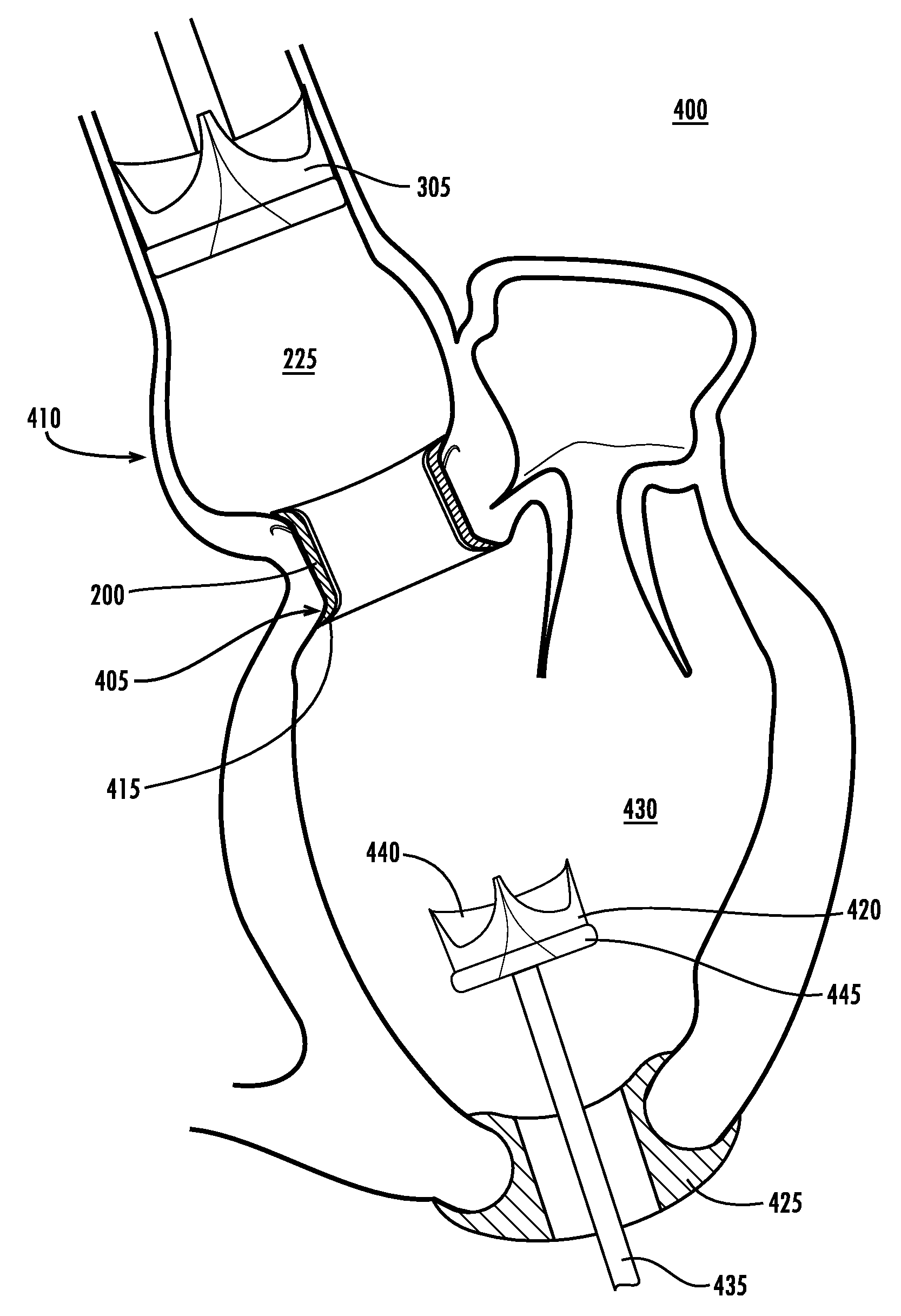
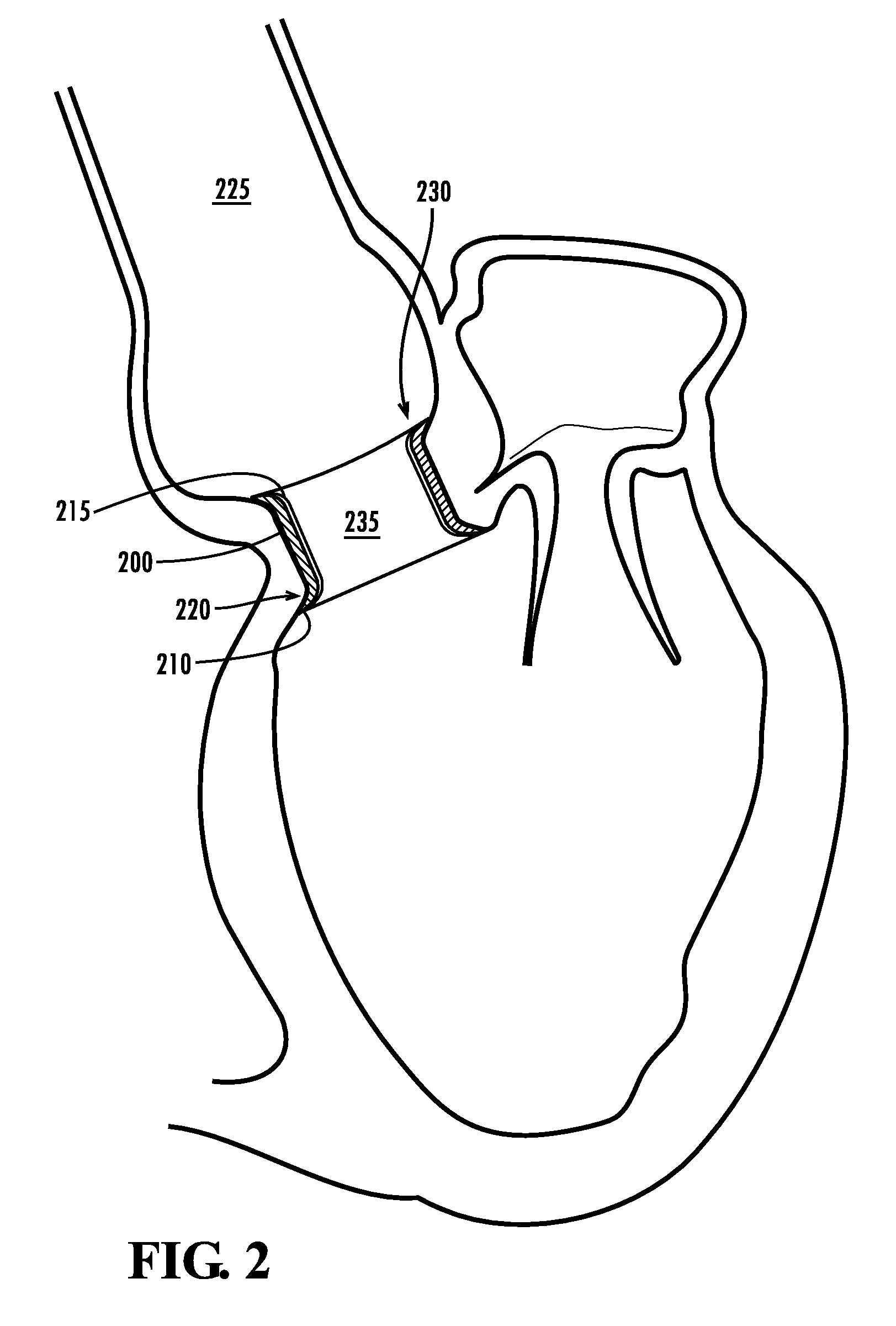
[0038]The present invention describes methods and apparatus to prepare a heart valve for replacement and improve a deficient heart valve. An exemplary embodiment of the method of preparing a heart valve for replacement involves delivering an anchoring conduit to a heart valve. The anchoring conduit is expanded in the heart valve and the expansion of the anchoring conduit disables the heart valve. Furthermore, the expansion of the anchoring conduit defines an open cavity.
[0039]An exemplary embodiment of the method of improving a deficient heart valve involves delivering an anchoring conduit to a heart valve. The ancho

Problems solved by technology

It is the leading cause of death in the U.S., killing some 950,000 people each year.
It also accounts for a significant amount of disability and diminished quality of life.
The performance of the cardiac cycle by the various components of the heart is a complex and intricate process.
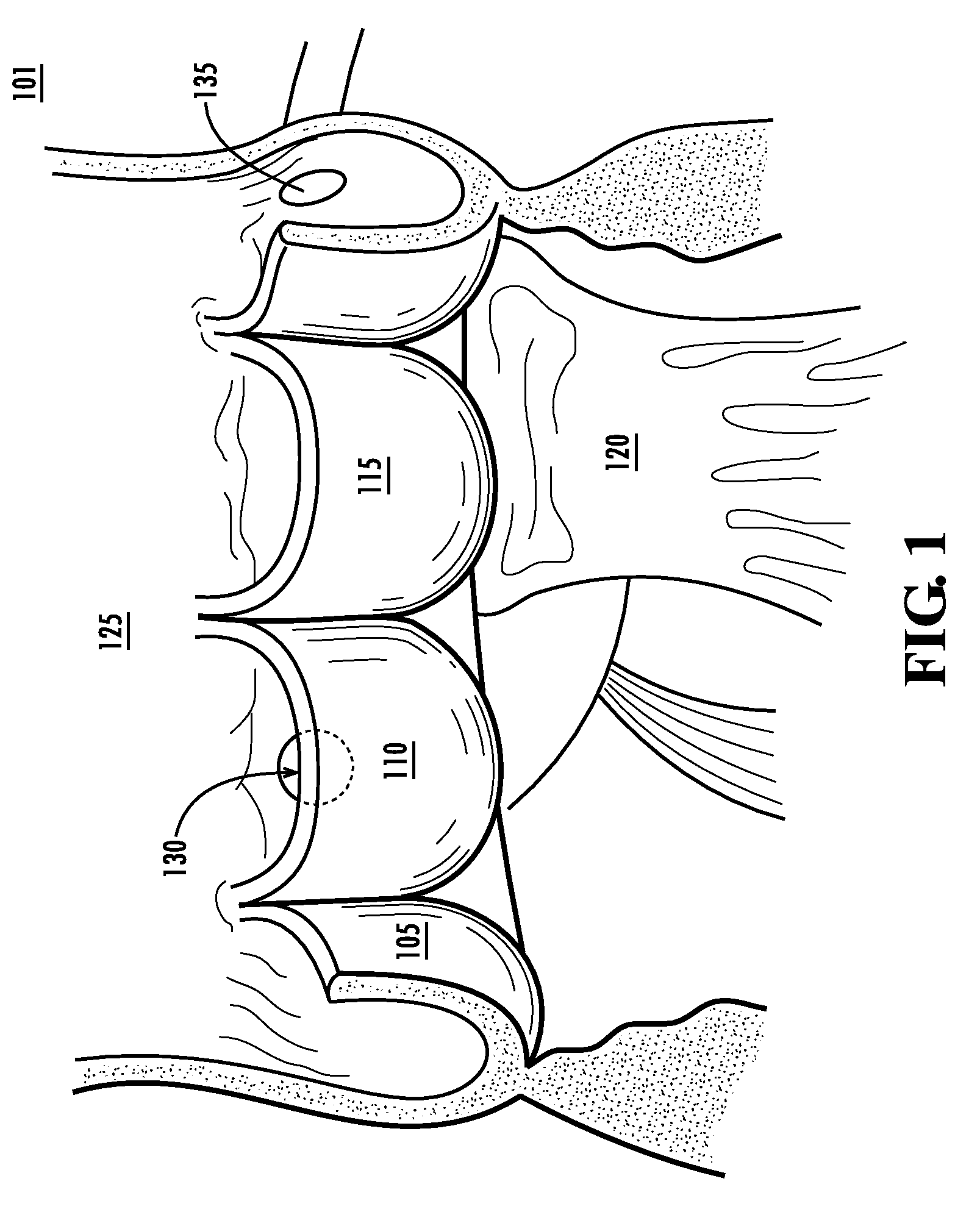
Incompetent closure of the aortic valve can result from intrinsic disease of the cusp, diseases of the aorta, or trauma.
Diastolic reflux through the aortic valve can lead to left ventricular volume overload.
If one of the components or functions of the complicated interaction fails, then aortic valve regurgitation can result.
Prolonged and / or severe aortic valve regurgitation can lead to compensatory left ventricle dilation.
Aortic valve regurgitation is a progressive condition that, if not corrected, can be fatal.
This backflow of blood can overload the right ventricle and lead to right ventricle dilation.
Despite their superior durability, the turbulent fluid mechanics of mechanical valves causes damage to blood cells.
This damage to the blood cells can include thrombus formation.
Further problems are associated with mechanical heart valves, including small stagnant regions proximate the hinges that sometimes lead to bacterial infections causing further heart damage.
Although polymeric valves show great promise they have been under development for several decades and no design has made it to commercialization due to failure or calcification within its normal biological environment.
As a result, mechanical valves are still the primary choice for surgical correction and have to be used in conjunction with anticoagulation therapies, which reduces the quality of life of the patient and exposes them to risks associated with bleeding.
As a result, the tissue comprising the valve is non-viable, and therefore, subject to degeneration with time.
Leaflet fixation stiffens the tissue unintentionally, alters internal shear properties, increases shear stiffness, stress relaxation and hysteresis, and causes substantial dehydration, all of which lead to valve failure due to calcification or tissue tearing.
Although some chemical treatments are effective in reducing calcification, they do not prevent disruption of collagen fibers.
Collagen fibers exposed to blood flow are damaged and cannot be repaired due to lack of viable cells within the leaflet.
Therefore because of tissue degradation and calcification bioprosthetic valves have a limited durability which may average around 10 years.
Although bioprosthetic valve technology has advanced, their limited durability is a problem which may take a long time to address completely.
While these bioprosthetic and mechanical valves present a number of improvements over the prior art, the safety and success of these devices is significantly reduced by the complexity of their deployment.
The deployment of these conventional bioprosthetic valves requires the precise execution of a number of steps and techniques, and inaccurate execution of even one of these steps can lead to a patient fatality.
Furthermore, a replacement valve positioned in an inadequately anchored valve will not be able to resist the forces of the constantly changing vessel wall diameter and turbulent blood flow.
Improper and insufficient deployment can lead to migration of the valve anchor before or after the deployment of the bioprosthetic valve.
Even the slightest migration of the valve anchor can have many detrimental results, including covering the openings to an arterial outlet or compromising the function of the replacement valve.
Not only is precise placement of the valve anchor of a bioprosthetic valve important, a secure seating of the valve anchor is critical because improper or insufficient deployment of the valve anchor can lead to leakage between the anchor and the lumen wall.
The typical calcification, thickening, and hardening of the cardiac annulus can make it increasingly difficult to achieve proper sealing quality for the valve anchor of the bioprosthetic valve.
For example, heavy calcification on the native valve can lead to bumpy and even surfaces, which can translate to a low quality seal of the valve anchor with the lumen wall if not deployed properly.
Not only can calcification make it difficult to properly seat the valve anchor, fragments of the calcified deposits can be loosened during the seating of the valve anchor and thus enter blood stream causing damage and possible blockage.
While many of the conventional devices have attempted to address the issues and complexities associated with the minimally invasive deployment of a heart valve replacement, significant problems and risks for the patient still exist.
A large majority of the risk is due to the nature of the deployment of the replacement valves.
Furthermore, the endovascular deployment of the heart valve provides a surgeon with a limited ability to verify the correctness and accuracy of the deployment.
This two dimensional image leaves a large amount of room for error in the three dimensional deployment of the replacement valve.
For example, the valve anchor could appear properly seated on the ultrasound image, but the side of the valve anchor not visible in the image could be misaligned and / or improperly sealed with the lumen wall.
As described, a slightly improper seal or slight misplacement of the valve anchor can lead to catastrophic and even fatal results.
Additionally, once the replacement valve has been fully deployed, it is difficult or impossible to change the position of the prosthesis without damaging the native structure.
As a result of the limitations of both bioprosthetic heart valve and mechanical valves, patients have to choose between quality of life and durability of the repair.
Additionally there is a group of patients which may not tolerate the risks associated with a mechanical valve, but may limit their lives using a bioprosthetic valve as a second operation to replace this valve can be considered clinically not viable.

Method used


Image

  • Systems and methods for enabling heart valve replacement
  • Systems and methods for enabling heart valve replacement
  • Systems and methods for enabling heart valve replacement

Examples


Embodiment Construction

[0051]The present invention addresses the deficiencies in the prior art by providing a minimally invasive apparatus and method for preparing a heart valve for replacement and for deploying a replaceable heart valve prosthesis. The apparatus and method of preparing a heart valve for replacement can be used to improve the success and efficacy of heart valve repair. The medical device and method of improving a deficient heart valve disclosed herein can be used to repeatedly deploy a heart valve prostheses within a deficient valve of the heart. Enabling the efficacious replacement of a heart valve can provide an effective manner of treating valvular heart disease without many of the drawbacks associated with conventional devices and methods. Significantly, the cardiac prosthesis system of the present invention provides a solution which does not force patients to choose between the quality of life associated with bioprosthetic valves and long term durability associated with mechanical va...


PUM


Abstract

The present invention describes a cardiac prosthetic system (400) comprising: an anchoring conduit (200) having a harbour (415), the harbour including a first releasably engaging component (515); a temporary valve (305) and a heart valve prosthesis (420) having a second releasably engaging component (445) enabled to be securely coupled and uncoupled from the first releasably engaging component (515) of the harbour (415).

Description

CROSS REFERENCE TO RELATED APPLICATIONS[0001]This application claims the benefit of U.S. Provisional Application No. 60 / 750,558, filed 15 Dec. 2005, which is hereby incorporated by reference in its entirety as if fully set forth below.FIELD OF THE INVENTION[0002]This invention refers generally to the field of heart valve replacement, and specifically to the implants tools and methods for preparing a native heart valve for a prosthesis and for providing a replaceable heart valve prosthesis.BACKGROUND OF THE INVENTION[0003]Cardiovascular disease accounts for nearly fifty percent of deaths in both the developed world and in developing countries. Indeed, the risk of dying from heart disease is greater than the risk from AIDS and all forms of cancer combined. Cardiovascular disease causes 12 million deaths in the world each year. It is the leading cause of death in the U.S., killing some 950,000 people each year. It also accounts for a significant amount of disability and diminished qual...

Claims


Application Information

Patent Timeline
IPC IPC(8): A61F2/24A61F2/04
CPCA61F2/2409A61F2/2412A61F2/2418A61F2250/006A61F2002/9528A61F2250/0059A61F2002/8483
Inventor YOGANATHAN, AJIT P.JIMENEZ, JORGE HERNAN
Owner GEORGIA TECH RES CORP
Learn More