Diagnostic system for automatic transmission

a diagnostic system and automatic transmission technology, applied in the direction of mechanical equipment, instruments, transportation and packaging, etc., can solve the problems of inability to release, deterioration of the shifting performance of the automatic transmission, and the diagnostic system still suffers a problem in terms of flexibility or freedom with which to perform fault diagnosis, so as to achieve a high degree of freedom and high reliability

Active Publication Date: 2009-06-18
TOYOTA JIDOSHA KK
View PDF2 Cites 10 Cited by
  • Summary
  • Abstract
  • Description
  • Claims
  • Application Information

AI Technical Summary

Benefits of technology

[0022]In general, the solenoid valve capable of regulating the hydraulic pressure of the hydraulic oil supplied to the friction device used for limp-home running of the vehicle, namely, the solenoid valve for use in limp-home running, is normally diagnosed with a relatively low frequency. However, if the solenoid valve for use in limp-home running goes out of order, the vehicle is not even able to run in the limp-home mode in the event of failure. Thus, the solenoid valve for use in limp-home running is especially required to be diagnosed at regular intervals. In the diagnostic s

Problems solved by technology

In the automatic transmission as described above, if a fault, such as disconnection or a short-circuit, occurs to a solenoid of any of the solenoid valves, the transmission may suffer a problem that, for example, a friction device to be engaged for shifting is not able to be engaged, or a problem that a friction device to be released for shifting is not able to be released.
In this case, the automatic transmission may not be able to be shifted to the target gear position, or the automatic transmission may lock i

Method used


Image

  • Diagnostic system for automatic transmission
  • Diagnostic system for automatic transmission
  • Diagnostic system for automatic transmission

Examples


Embodiment Construction

[0031]In the following description and the accompanying drawings, the present invention will be described in more detail with reference to exemplary embodiments.

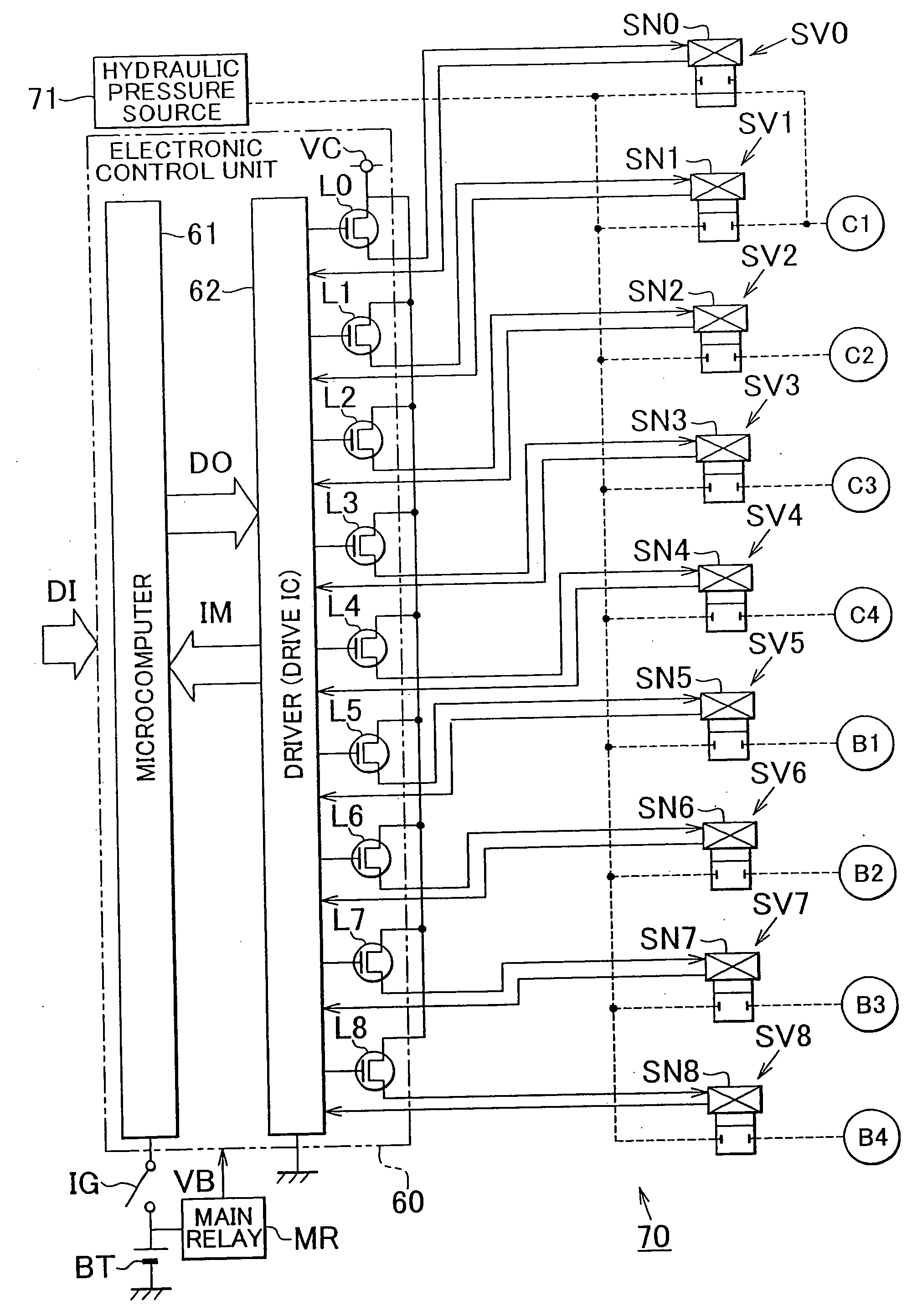
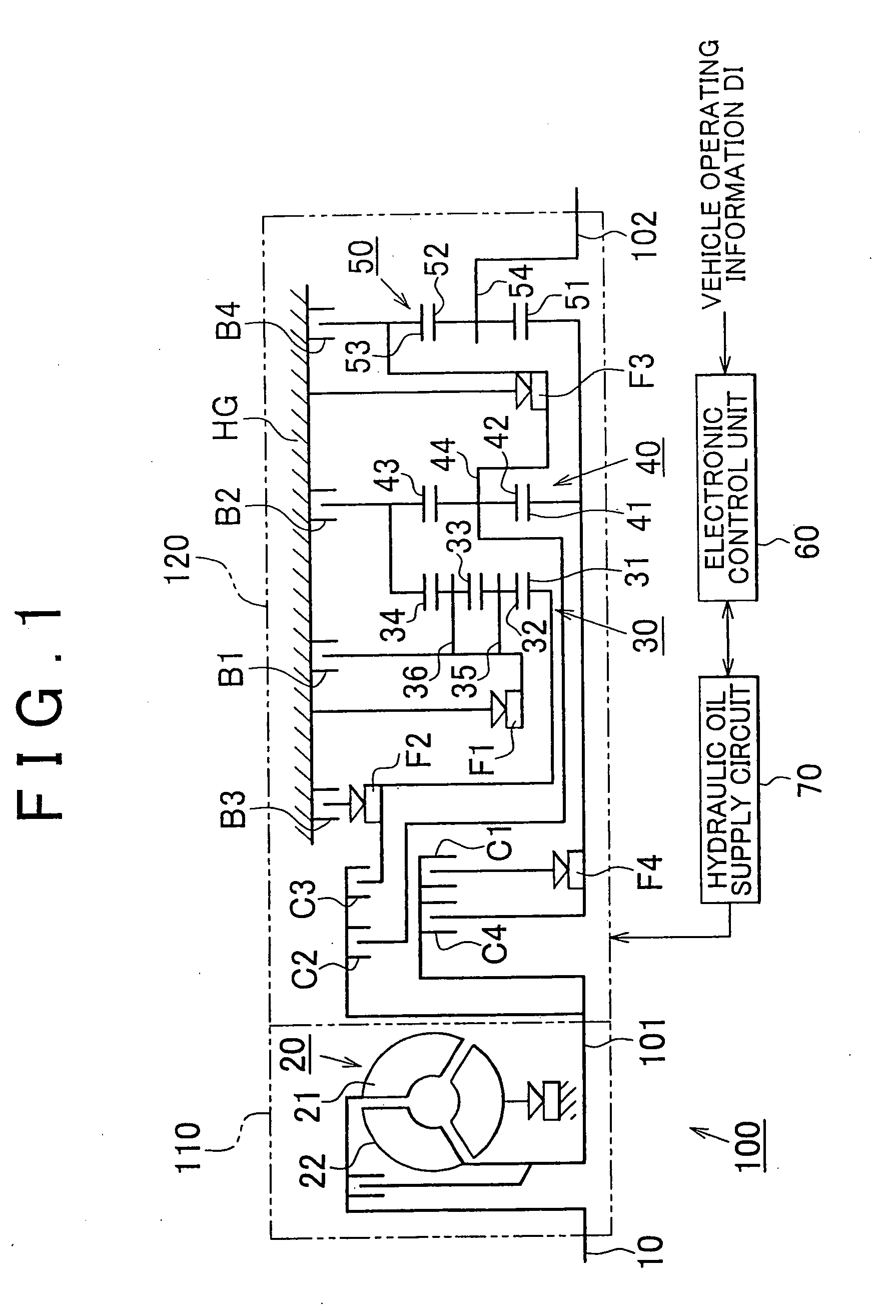
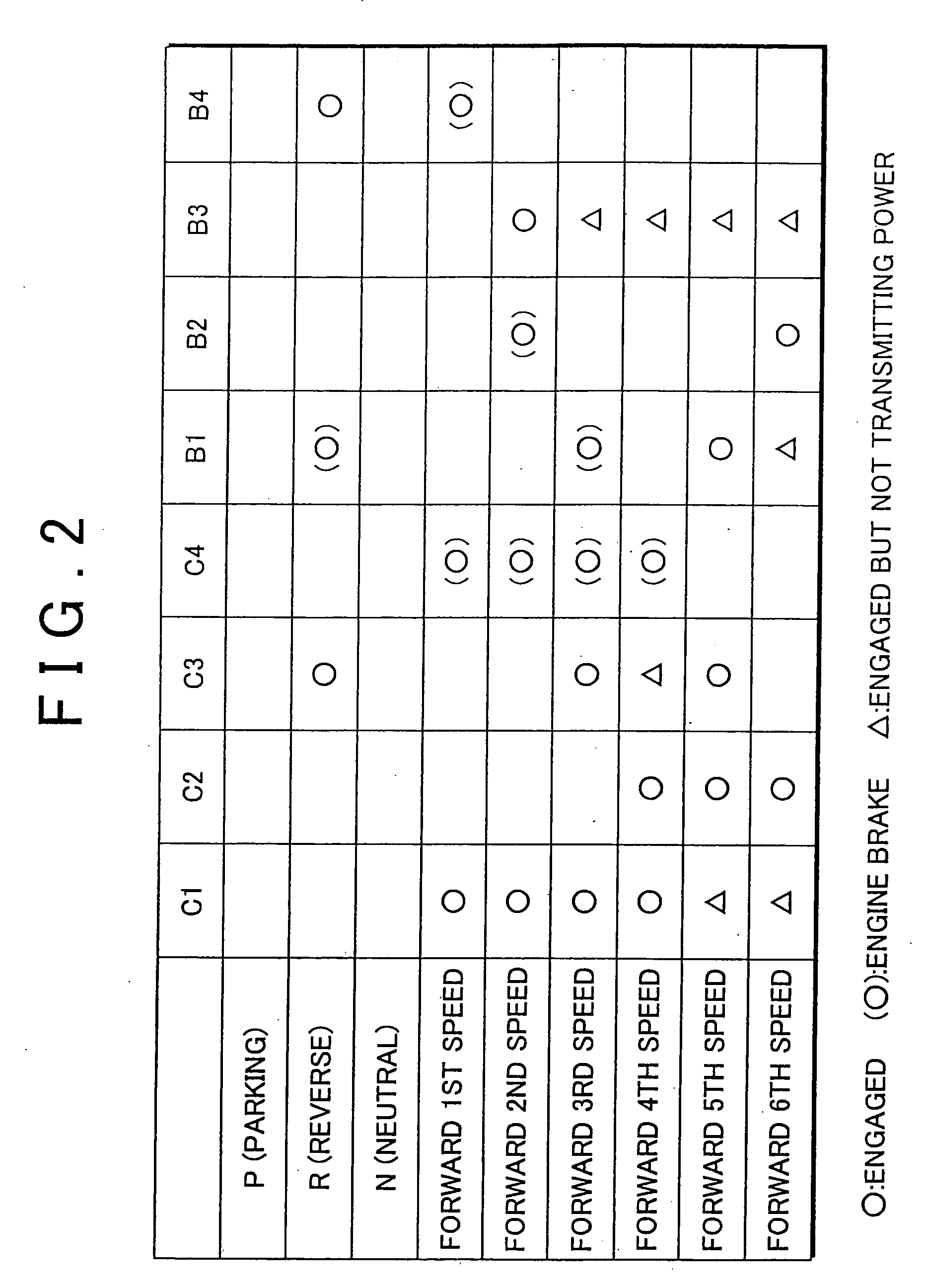
[0032]Referring to FIG. 1 through FIG. 4, a diagnostic system for an automatic transmission according to one embodiment of the invention will be described in detail. In this embodiment, the invention is applied to a diagnostic system for a forward six-speed automatic transmission installed on a vehicle. As shown in FIG. 1, the automatic transmission 100 consists principally of an input conversion unit 110 connected to a crankshaft 10 of an internal combustion engine as one example of prime mover installed on the vehicle, and a gear train unit 120 connected to driving wheels of the vehicle via a propeller shaft. The input conversion unit 110 includes a torque converter 20. As well known in the art, the torque converter 20 includes a pump impeller 21 coupled to the crankshaft 10, and a turbine runner 22 coupled to an input sha...


PUM


Abstract

A diagnostic system for an automatic transmission is provided in which a microcomputer determines that torque that can drive the driving wheels of the vehicle is not transmitted to an output shaft of the automatic transmission when the vehicle is stopped and the ignition key is operated to the OFF position, and performs forced energization of solenoids of solenoid valves associated with respective friction devices of the transmission, while monitoring current passing through the solenoid valves. If the current monitored does not match the current for energizing any of the solenoids, the microcomputer determines that the corresponding solenoid valve is at fault. Thus, the diagnostic system appropriately determines the presence of a fault of each solenoid valve for controlling the hydraulic pressure to each friction device, with increased flexibility and freedom.

Description

BACKGROUND OF THE INVENTION[0001]1. Field of the Invention[0002]The invention relates to a diagnostic system for an automatic transmission, which diagnoses an automatic transmission installed in a drive train of a vehicle to determine the presence of faults therein.[0003]2. Description of the Related Art[0004]As well known in the art, an automatic transmission installed in a drive train of the vehicle includes a plurality of friction devices, such as clutches and brakes, to which hydraulic pressure is selectively applied so as to engage the friction devices. With the selected friction device(s) thus engaged, a power transmission path, or a gear position of the transmission, is determined depending upon the operating conditions of the vehicle. More specifically, a hydraulic pressure source is provided which is driven through rotation of an output shaft of an internal combustion engine so as to supply hydraulic oil to each of the friction devices, and a plurality of solenoid valves ar...

Claims


Application Information

Patent Timeline
IPC IPC(8): F16H61/12F16H59/68F16H59/74F16H61/68F16H61/684F16H61/686F16H63/50
CPCF16H61/12F16H61/686F16H2061/1208F16H2061/1268F16H2200/201F16H2200/2051F16H2200/0052F16H59/68F16H61/00
Inventor NIWA, KENJISUGIMURA, TOSHIOMIZOBUCHI, MASAYASU
Owner TOYOTA JIDOSHA KK
Why Eureka
Try Eureka