Optical information recording apparatus and method

a technology of optical information and recording apparatus, applied in the direction of optical recording/reproducing/erasing methods, instruments, optical beam sources, etc., can solve the problems of linear recording being disabled, reducing the signal-to-noise ratio, and the negative effect of high-density recording

Inactive Publication Date: 2009-06-25
KK TOSHIBA
View PDF6 Cites 31 Cited by
  • Summary
  • Abstract
  • Description
  • Claims
  • Application Information

AI Technical Summary

Problems solved by technology

When hologram recording is performed, the spot has generally much higher intensity as compared to that in the other regions, and this causes negative effects of high-density recording.
Namely, a high-brightness 0th-order beam spot exceeds a dynamic range of the holographic-memory recording medium, which causes linear recording to be disabled, and this leads to a decrease in a signal-to-noise (SN) ratio.
High-brightness 0th-order beam spots overlap upon multiple recording, and the location of the 0th-order beam spot in the holographic-memory recording medium is thereby excessively exposed and consumed.
This is because t...

Method used


Image

  • Optical information recording apparatus and method
  • Optical information recording apparatus and method
  • Optical information recording apparatus and method

Examples


first embodiment

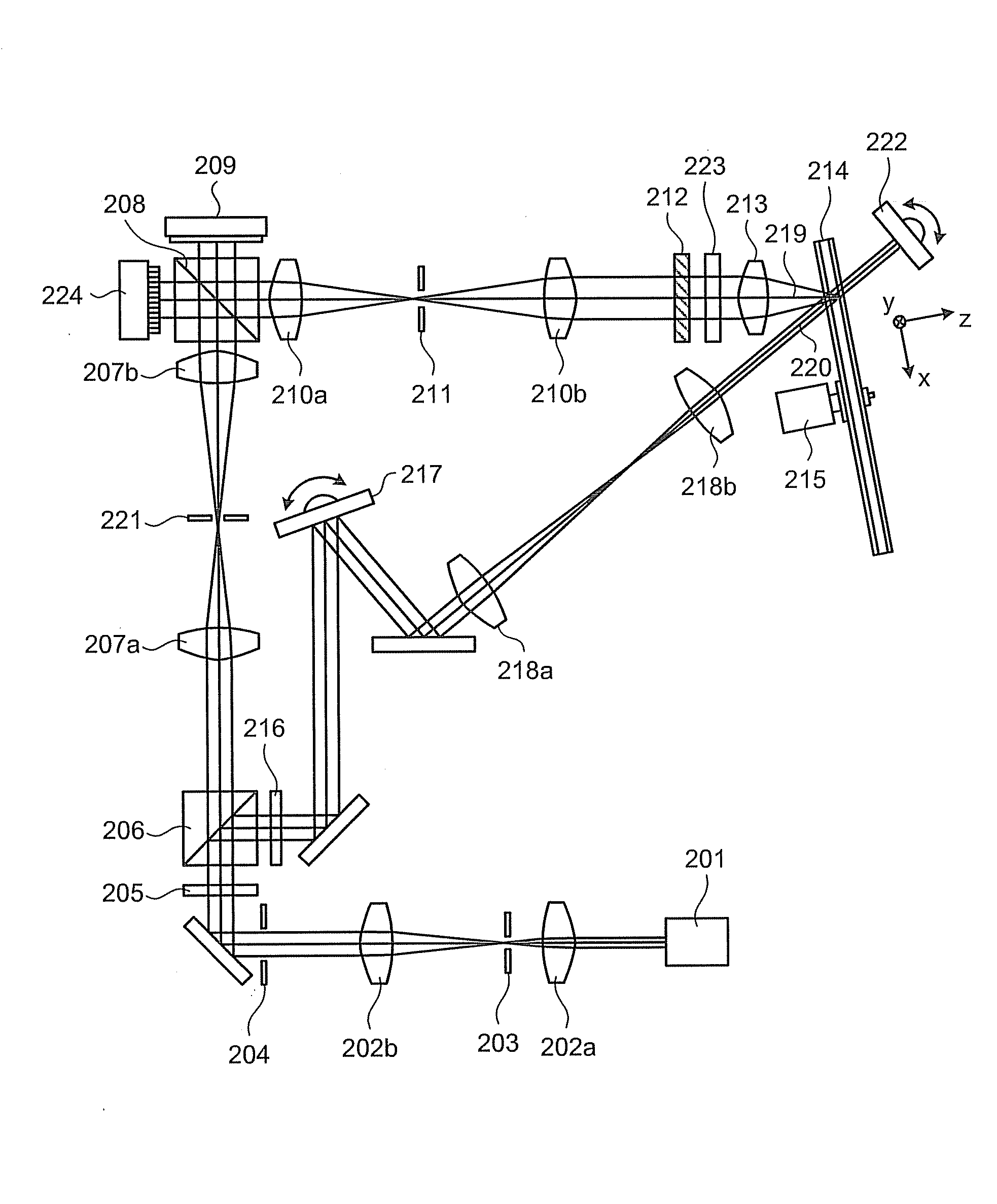
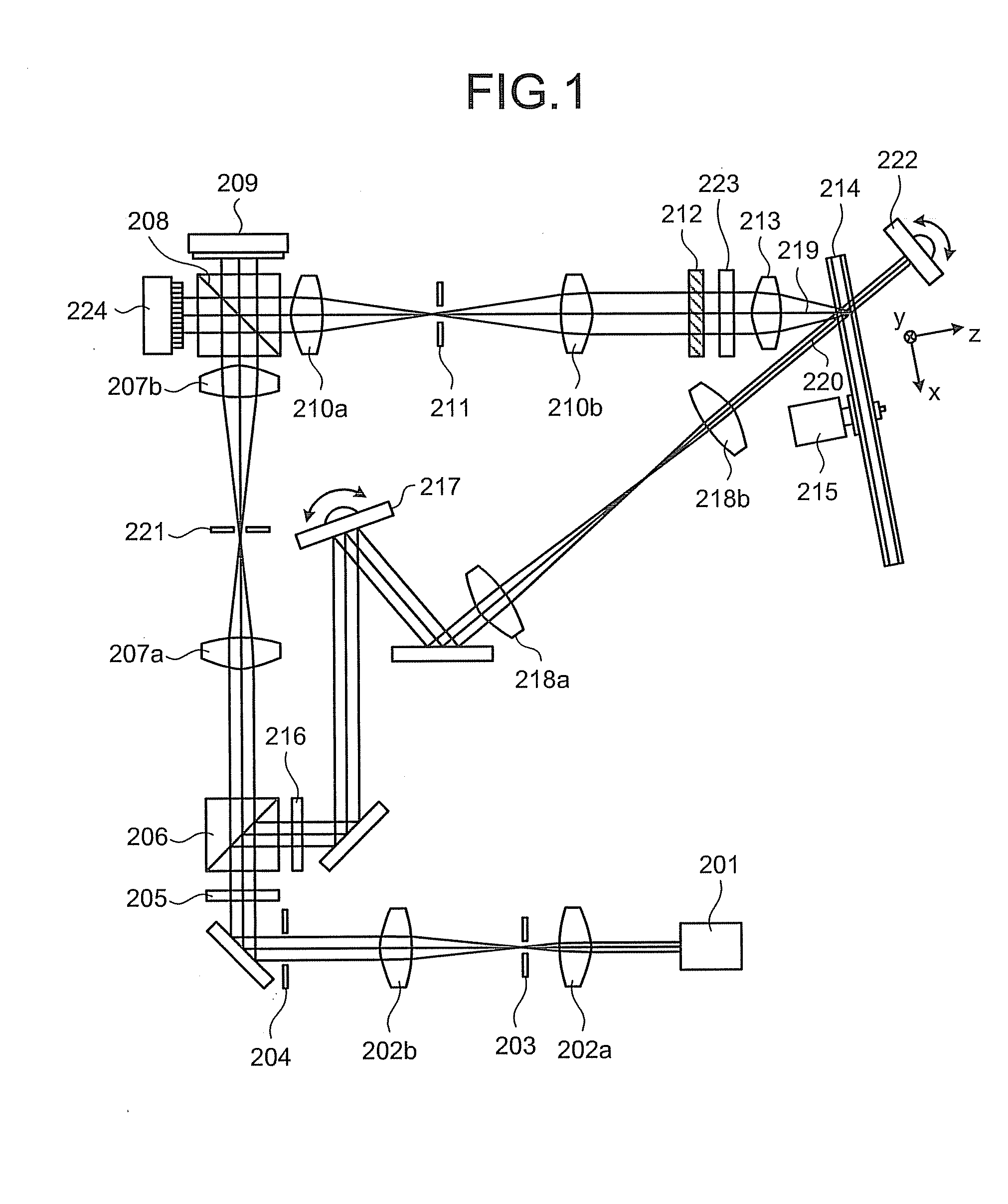
[0046]As shown in FIG. 1, first embodiment of the present invention employs an optical system of a two light flux system in which an information beam and a reference beam are made incident on a holographic-memory recording medium 214 through discrete objective lenses so as to overlap each other on the holographic-memory recording medium 214. However, the optical system is not limited to the two light flux system, and thus a colinear system may be employed as the optical system. The colinear system is such that the information beam and the reference beam are made incident on the holographic-memory recording medium 214 from the same direction through one objective lens or the like so as to share the same central axis thereof.

[0047]A semiconductor laser device 201 is a laser light source that emits a laser beam. To improve quality of recording and reproduction, the laser beam emitted from the semiconductor laser device 201 enters a spatial filter formed with a relay lenses 202a and 202...

second embodiment

[0095]As explained above, in the second embodiment, the phase mask 712 is placed between the semiconductor laser device 201 and the spatial light modulator 209 at the position where the boundaries in the regions of the phase mask 712 coincide with the boundaries in the data region of the two-dimensional modulation pattern emitted from the spatial light modulator 209. Therefore, there is no need for high-accuracy alignment, and the 0th-order beam in the Fourier plane can be reduced in the hologram recording / reproducing system while preventing the degradation of the reproduced image.

[0096]The position of the phase mask 712 is not limited to the position according to the second embodiment if the phase mask 712 is placed in the above manner. For example, the phase mask can also be structured so as to be integrally formed with the spatial light modulator.

[0097]As shown in FIG. 8, in a modification of the second embodiment, a phase mask 812 is placed between the semiconductor laser device...

third embodiment

[0101]In the third embodiment, as shown in FIG. 9, a phase mask 912 is placed between a spatial light modulator 909 and the holographic-memory recording medium 214 at a position where a two-dimensional modulation pattern of the information beam 219 emitted from the spatial light modulator 909 is imaged by the relay lenses 210a and 210b.

[0102]Here, the phase mask 912 according to the third embodiment uses a liquid crystal panel, and a voltage is applied to the phase mask 912 by a phase-mask drive unit 902, to thereby cause a phase imparted to the information beam 219 to be electrically variable.

[0103]In the third embodiment, a digital micromirror device (DMD) is used as the spatial light modulator 909.

[0104]Moreover, the third embodiment is configured to place a Fourier transform lens 905 at a position where the reference beam 220 passes through the transmission holographic-memory recording medium 214, and to receive a reproduction beam having passed through the holographic-memory r...


PUM


Abstract

An optical information recording apparatus includes a light source that emits an irradiation beam; a spatial light modulator that converts the irradiation beam to an information beam, the information beam having a two-dimensional modulation pattern that carries information and is formed with a plurality of first regions in which each of boundaries is formed with OFF pixels; a phase modulator that includes a plurality of second regions, and that imparts the phases to the irradiation beam or the information beam to modulate phases of the irradiation beam or the information beam; and a light collector that collects the information beam and a reference beam on an optical information recording medium that can record the information as hologram, by using interference fringes produced due to interference between the information beam and the reference beam.

Description

CROSS-REFERENCE TO RELATED APPLICATIONS[0001]This application is based upon and claims the benefit of priority from the prior Japanese Patent Application No. 2007-324941, filed on Dec. 17, 2007; the entire contents of which are incorporated herein by reference.BACKGROUND OF THE INVENTION[0002]1. Field of the Invention[0003]The present invention relates to an optical information recording apparatus and method for recording information as hologram in an optical information recording medium.[0004]2. Description of the Related Art[0005]Recently, among various approaches, a volume-recording type high-density optical recording using holography (hereinafter, “holographic memory”) and a recording / reproducing device of the holographic memory (hereinafter, “holographic-memory recording / reproducing device”) are being developed for practical use.[0006]A recoding principle of a hologram recording system is that information is three-dimensionally recorded as fine interference fringes by causing a...

Claims


Application Information

Patent Timeline
IPC IPC(8): G11B7/00
CPCG03H2210/22G03H2223/13G11B7/128G11B7/0065G11B7/00772G03H2225/31
Inventor YAMAMOTO, YUICHIROTATSUTA, SHINICHI
Owner KK TOSHIBA
Why Eureka
Try Eureka