Display Apparatus and Method of Manufacturing a Display Apparatus

a technology of display apparatus and manufacturing method, which is applied in the field of display apparatus, can solve the problems of warped display device, difficult to reduce the thickness of the adhesive sheet obtained by bonding a silicone sheet and a silicone gel layer together, and increase the chance of air bubbles particularly on the ic side, so as to reduce the size, reduce the unevenness of displayed images, and avoid peeling

Inactive Publication Date: 2009-06-25
SEIKO INSTR INC
View PDF4 Cites 61 Cited by
  • Summary
  • Abstract
  • Description
  • Claims
  • Application Information

AI Technical Summary

Benefits of technology

[0015]The present invention has been made in view of the above-mentioned problems, and therefore has an object to provide a liquid crystal display device integrated with a cover plate or a touch panel that is reliable in terms of less unevenness in displayed images and the like and no peeling, that has substantially no fear of an adhesive protruding from its designated space, and that can be reduced in size.

Problems solved by technology

The glass substrate of the display device to which a driver IC is mounted by COG is warped by about 20 μm, which increases the chance of trapping air bubbles particularly on the IC side.
It is very difficult to bond a 1.5 mm-thick acrylic plate to a warped display device by adhesion.
An adhesive sheet obtained by bonding a silicone sheet and a silicone gel layer together is difficult to reduce its thickness.
However, bonding a liquid crystal display device and a cover plate with a transparent liquid adhesive has the following problems.
The uniformity of gaps between liquid crystal molecules is therefore lost in an environment test, making images and the like that are displayed look uneven.
Shrinkage stress generated as the liquid adhesive cures is therefore larger in the level difference portion and changes the gaps in the liquid crystal layer, resulting in unevenness in displayed images and the like.
The gaps between liquid crystal molecules are also changed by a pushing pressure from the cover plate, and the change causes great unevenness in displayed images and the like particularly in an area near the perimeter of the display screen.
The liquid adhesive bonding the liquid crystal display device and the cover plate sometimes protrudes past the perimeter of the liquid crystal display device such that the liquid crystal display device cannot be housed in a plastic frame.
The transparent adhesive under the electrode portion or the printed member continues to cure gradually even after light irradiation is finished, thus generating curing shrinkage stress, which changes the gaps between liquid crystal molecules and makes displayed images and the like look uneven.
This unevenness in displayed images and the like occurs a few days later in most cases.

Method used


Image

  • Display Apparatus and Method of Manufacturing a Display Apparatus
  • Display Apparatus and Method of Manufacturing a Display Apparatus

Examples


embodiment 1

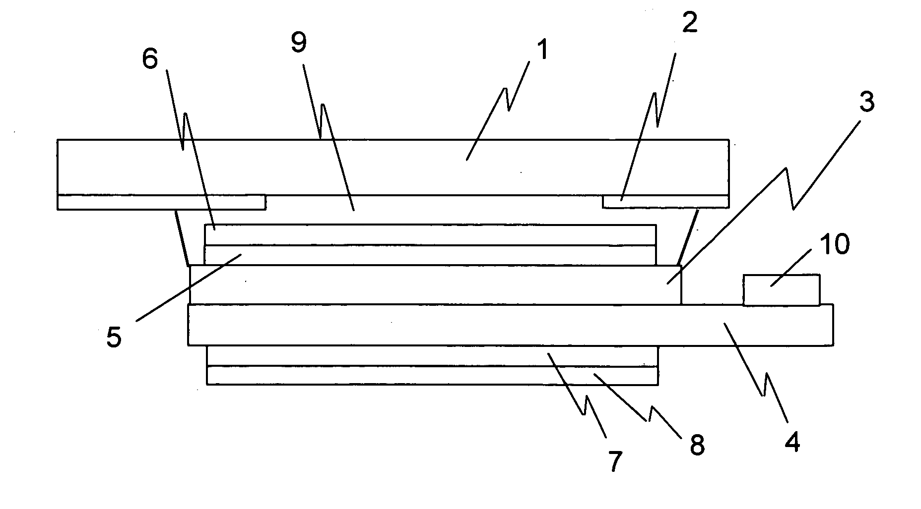
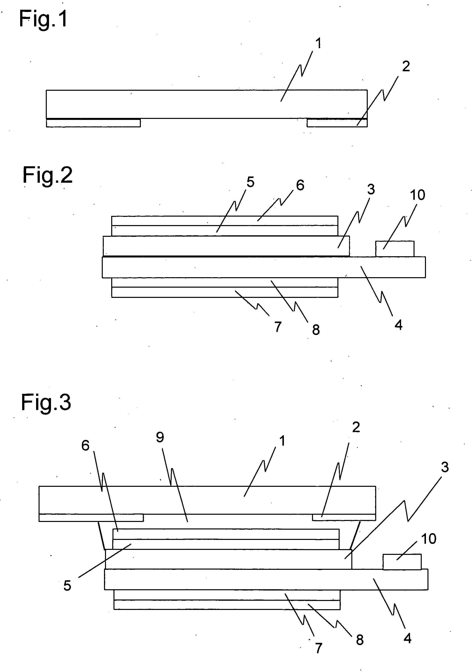
[0027]An embodiment of the present invention is described below with reference to the accompanying drawings. FIG. 1 is a side view of a transparent cover plate. The transparent cover plate is denoted by 1 and is made of chemically reinforced soda glass. On a rear surface of the transparent cover plate 1, in an area that falls on the perimeter of a display portion, black ink 2 is applied by printing. The transparent cover plate 1 is 1.5 mm in thickness and the layer of the ink 2 is about 12 μm in thickness. A metal thin film may be formed between the glass and the print. FIG. 2 is a side view of a liquid crystal display device. A glass substrate 4 on which TFT elements are formed and which has a thickness of 0.25 mm and a glass substrate 3 on which a color filter and an electrode are formed face each other across a gap where a liquid crystal is placed. A phase difference correction film 5 and a polarizing film 6 are attached to the display side of the liquid crystal display device. S...


PUM

PropertyMeasurementUnit
thicknessaaaaaaaaaa
thicknessaaaaaaaaaa
thicknessaaaaaaaaaa

Abstract

A display apparatus is provided in which a transparent cover plate or a touch panel is bonded to a liquid crystal display device in a full-surface contact manner and which is free from unevenness in displayed colors and peeling. The transparent cover plate or touch panel and the liquid crystal display device are bonded with an optical adhesive, which is set to a Shore A hardness of 1 or more to 30 or less. The thickness of the adhesive layer is set to 30 to 200 μm.

Description

BACKGROUND OF THE INVENTION[0001]1. Field of the Invention[0002]The present invention relates to a display apparatus in which a transparent member and a display device are bonded together with a liquid adhesive in a full-surface contact manner. For example, the present invention relates to bonding a transparent cover plate such as an acrylic plate or a polycarbonate plate, or a touch panel having a glass-glass, film-glass, or film-film structure such as an analog resistive film touch panel, a digital resistive film touch panel, a capacitive (CAP) touch panel, or a surface acoustic wave (SAW) touch panel, to a display device such as a liquid crystal display device, a plasma display, an organic EL display, an inorganic EL display, or an FED in display apparatuses including PDAs and cellular phones.[0003]2. Description of the Related Art[0004]A common conventional way to fix a transparent touch panel to a display device is to place a double-sided adhesive cushion with a thickness of 0....

Claims


Application Information

Patent Timeline
Patent Type & Authority Applications(United States)
IPC IPC(8): B32B7/00B32B37/00
CPCG02F1/1333G02F1/13338Y10T428/26G02F2202/023G02F2202/28G02F2001/133388G02F1/133388G02F1/1335G02F1/1339
Inventor MATSUHIRA, TSUTOMU
Owner SEIKO INSTR INC
Why Eureka
Try Eureka