Chemical suppressors and method of use

a technology of suppressors and suppressors, applied in the field of chemical suppressors, can solve the problems of increased noise, high voltage (50-500 volts dc) required, and detrimental to effective detection

Inactive Publication Date: 2009-07-02
DIONEX CORP
View PDF18 Cites 8 Cited by
  • Summary
  • Abstract
  • Description
  • Claims
  • Application Information

AI Technical Summary

Benefits of technology

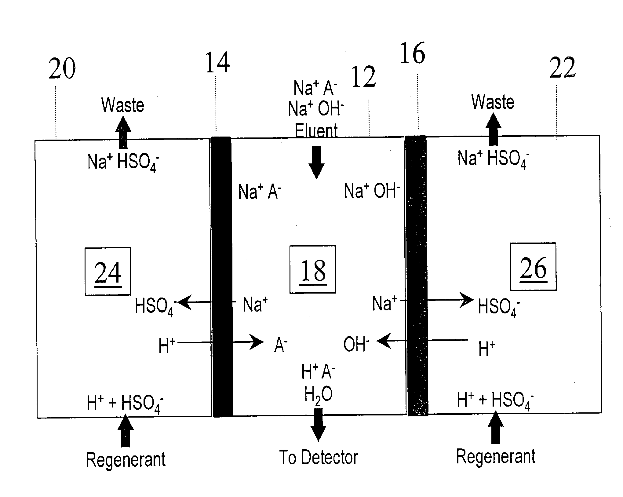
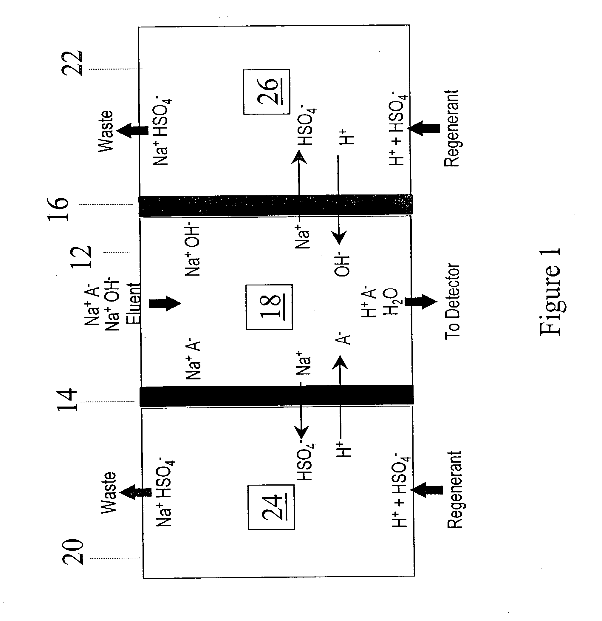
[0018]In another embodiment, a non-electrolytic method is provided for treating an aqueous sample stream including analyte ions of one charge and matrix ions of opposite charge to the analyte ions. The method comprises flowing the sample stream through a sample stream flow channel, simultaneously flowing an aqueous stream through an ion receiving flow channel separated therefrom by a first ion exchange membrane capable of passing only ions of opposite charge to the analyte ions and of blocking bulk liquid flow to reduce the concentration of the matrix ions in an effluent from the sample stream flow channel, the sample stream flow channel having stationary flow-through first packing of ion exchange material disposed in the sample stream flow channel of the same charge as the first membrane and having a first ion exchange capacity for the matrix ions. The ion receiving channel has an ion exchange capacity for the matrix ions less than about 25% of the first ion exchange capacity for the matrix ion. No electric field is applied between the sample stream flow channel and the first ion receiving flow channel.
[0019]In another embodiment, a chromatography method is provided comprising flowing an aqueous sample stream including analyte ions of one charge and matrix ions of opposite charge to the analyte ions through a chromatography separator to separate the analyte ions. The sample stream including the separated analyte ions flows through a sample stream flow channel, and simultaneously flowing an aqueous stream through an ion receiving flow channel separated therefrom by a first ion exchange membrane capable of passing only ions of opposite charge to the analyte ions and of blocking bulk liquid flow to reduce the concentration of the matrix ions in an effluent from the sample stream flow channel, the sample stream flow channel having stationary flow-through first packing of ion exchange material disposed in the sample stream flow channel of the same charge as the first membrane and having a first ion exchange capacity for the matrix ions, the ion receiving channel having an ion exchange capacity for the matrix ions less than about 25% of the first ion exchange capacity for the matrix ion.

Problems solved by technology

One problem with this electrodialytic membrane suppressor system is that very high voltages (50-500 volts DC) are required.
Such heat is detrimental to effective detection because it greatly increases noise and decreases sensitivity.
One problem with this form of suppressor is limited exchange capacity.
High concentrations of eluents, however, are not easily suppressed.

Method used


Image

  • Chemical suppressors and method of use
  • Chemical suppressors and method of use

Examples


example 1

[0048]The performance in terms of dynamic capacity of a standard AMMS III suppressor from Dionex Corporation was compared to a device of the present invention. The device of the present invention was assembled by fitting neutral regenerant screens in place of the functionalized cation exchange regenerant screens and using standard AMMS III suppressor components. A Dionex DX500 ion chromatography system was used for this testing. The dynamic suppression capacity was determined by pumping at 1 ml / min various concentrations of NaOH by conventional proportioning. The regenerant was 100 mN sulfuric acid pumped at 10 ml / min (conventional chemical suppression mode).

[0049]Results: The dynamic capacity of the standard AMMS III suppressor was measured as 170 ueqv / min. The device of the present invention showed a dynamic capacity of 210 ueqv / min which was an increase of 23% in capacity. Thus, removing the retention of the eluent cation in the regenerant chamber as per the current invention res...

example 2

[0050]The experimental setup was similar to Example 1 except the regenerant was 150 mN sulfuric acid and was dispensed using the displacement chemical regeneration approach of U.S. Pat. No. 6,436,719.

[0051]Results: The dynamic capacity under these conditions for a standard suppressor was 70 ueqv / min. The device of the present invention on the other hand showed a capacity of 90 ueqv / min. A 29% increase in capacity was observed as per the present invention.

example 3

[0052]The performance in terms of dynamic capacity of a standard CMMS III suppressor from Dionex Corporation was compared to a device of the present invention. The device of the present invention was assembled by fitting neutral regenerant screens in place of the functionalized regenerant screens using standard CMMS III suppressor components. A DX500 ion chromatography system was used for this testing. The dynamic suppression capacity was determined by pumping at 1 ml / min various concentrations of MSA by conventional proportioning. The regenerant was 100 mN tetrabutylammonium hydroxide base pumped at 10 mil / min (conventional chemical suppression mode). The dynamic capacity of the standard CMMS III suppressor was measured as 65 ueqv / min.

[0053]Results: The device of the present invention showed a dynamic capacity of 100 ueqv / min which was an increase of 53% in capacity. Thus, removing the retention of the anion in the regenerant chamber as per the present invention resulted in improve...


PUM

PropertyMeasurementUnit
voltagesaaaaaaaaaa
thickaaaaaaaaaa
thickaaaaaaaaaa

Abstract

A non-electrolytic method and apparatus for treating an aqueous sample stream including analyte ions and matrix ions of opposite charge, for pretreatment or suppression. The apparatus includes an ion exchange membrane capable of passing only ions of opposite charge to the analyte ions, a sample stream flow channel, a first aqueous stream ion receiving flow channel adjacent one side of the sample stream flow channel and separated therefrom by the first ion exchange membrane, and stationary flow-through ion exchange packing disposed in the sample stream flow channel. The ion receiving channel has an ion exchange capacity for the matrix ions less than about 25% of the ion exchange capacity for the matrix ions.

Description

CROSS-REFERENCE TO RELATED APPLICATION[0001]This application is a divisional application of U.S. application Ser. No. 10 / 356,345, filed on Jan. 30, 2003.BACKGROUND OF THE INVENTION[0002]The present application relates to a chemical suppression device and method for reducing the concentration of matrix ions of opposite charge to ions to be analyzed, and specifically for use of an ion chromatography suppressor or to a pretreatment device.[0003]Ion chromatography is a known technique for the analysis of ions which typically includes a chromatographic separation stage using an eluent containing an electrolyte, and an eluent suppression stage, followed by detection, typically by an electrical conductivity detector. In the chromatographic separation stage, ions of an injected sample are eluted through a separation column using an electrolyte as the eluent. In the suppression stage, electrical conductivity of the electrolyte is suppressed but not that of the separated ions so that the latt...

Claims


Application Information

Patent Timeline
Patent Type & Authority Applications(United States)
IPC IPC(8): B01D15/08B01D15/10G01N30/96B01D15/36B01D61/48
CPCB01D15/367Y10T436/25G01N30/96B01D61/48B01D61/52B01D61/54B01D2325/42
Inventor SRINIVASAN, KANNANPOHL, CHRISTOPHER A.
Owner DIONEX CORP
Why Eureka
Try Eureka