Techniques for providing a multimode ion source

a technology of ion source and multi-mode, which is applied in the direction of electric discharge tubes, instruments, measurement devices, etc., can solve the problems of large space charge problems, inefficient transport of low-energy ion beams by conventional ion implanters utilizing ihc ion sources, and ineffective implantation of dopant species at both low and high energies

Inactive Publication Date: 2009-07-02
VARIAN SEMICON EQUIP ASSOC INC
View PDF2 Cites 28 Cited by
  • Summary
  • Abstract
  • Description
  • Claims
  • Application Information

AI Technical Summary

Benefits of technology

[0013]Technique for providing a multimode ion source are disclosed. In one particular exemplary embodiment, the techniques may be realized as an apparatus for ion implantation, the apparatus may include an ion source having a hot cathode and a high frequency plasma generator, wherein the ion source may have multiple modes of operation.

Problems solved by technology

A problem that currently exists in conventional ion implantation is that conventional ion implanters cannot effectively implant dopant species at both low energies (e.g., sub-kev) and high energies (e.g., keV).
For example, conventional ion implanters utilizing an IHC ion source are relatively inefficient at transporting low-energy ion beams due to space charge within the ion beams.
In general, the lower the energy, the greater the space charge problems.
Therefore, it may be understood why conventional ion sources are not reliable in commercial production.
Furthermore, ion source vaporizers typically cannot operate reliably at the low temperatures required for decaborane, due to radiative heating from the ion source to the vaporizer that causes thermal instability of the molecules.
For example, vaporizer feed lines easily become clogged with boron deposits from decomposed vapor as the decaborane vapor interacts with their hot surfaces.
Additionally, a conventional ion source is generally incompatible with decaborane ion implantation and / or ion implantation using any other molecular species.
Thus, a conventional ion source may only be satisfactory for atomic and small molecular ions.
Although a high axial magnetic field improves the yield of multiply charged ions, this two-region ion source cannot produce sufficiently high intensity electron beams because of high-frequency instabilities and leads to poor ionization of atomic species.
As a result, a conventional ion source cannot reliably be used in high current ion implantation situations.
Furthermore, in this example, filament lifetime is relatively short because of sputtering of heavy ions.
Such extremely high temperatures shorten the performance and lifetime of IHC ion sources.
As a result, the performance degradation and short lifetime of IHC ion sources greatly reduce the productivity of ion implanters.
While these temperatures are generally required for thermal dissociation and atomic creation during implantation, they are not conducive for producing large molecular ions.
In view of the foregoing, it may be understood that there are significant problems and shortcomings associated with current ion source technologies.

Method used


Image

  • Techniques for providing a multimode ion source
  • Techniques for providing a multimode ion source
  • Techniques for providing a multimode ion source

Examples


Embodiment Construction

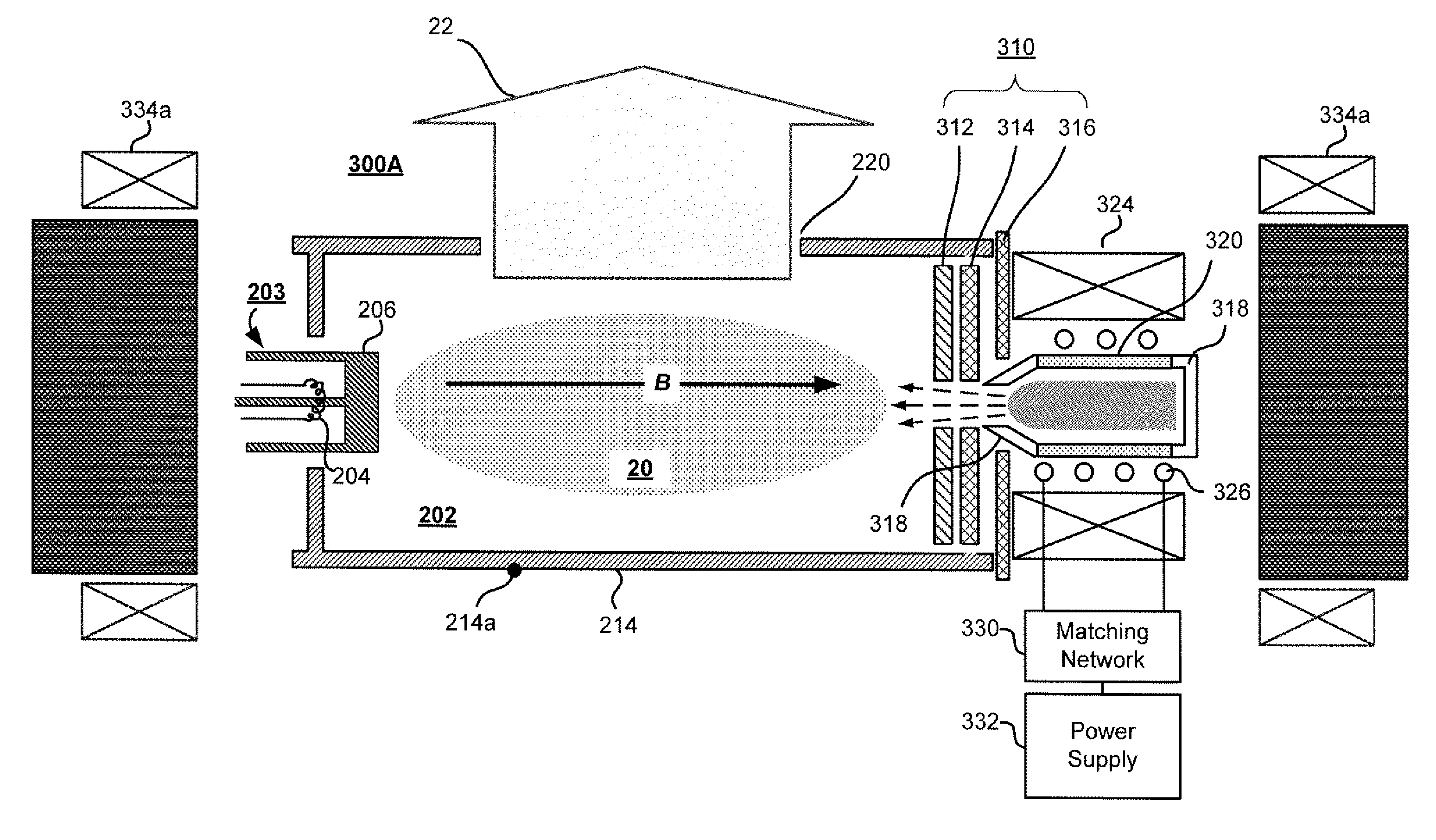
[0036]Embodiments of the present disclosure to provide a multimode ion source having greater molecular ion implantation as well as increased ion source performance and lifetime over conventional ion source technologies. In addition, embodiments of the present disclosure provide various exemplary ion source configurations.

[0037]Referring to FIG. 3A, a multimode ion source 300A is shown in accordance with an embodiment of the present disclosure. The multimode ion source 300A may have several modes of operation. These may include at least an arc-discharge mode and a non-arc-discharge mode. An arc-discharge mode of operation may include a hot cathode (HC) (e.g., an indirectly heated cathode (IHC)) mode of operation. An non-arc-discharge mode of operation may include a high frequency mode, a cold plasma cathode (CPC) mode, or a radio frequency (RF) mode. Other various modes of operation may also be provided, including other indirect or high frequency modes of operation.

[0038]Similar to t...


PUM


Abstract

Techniques for providing a multimode ion source are disclosed. In one particular exemplary embodiment, the techniques may be realized as an apparatus for ion implantation, the apparatus including an ion source having a hot cathode and a high frequency plasma generator, wherein the ion source has multiple modes of operation.

Description

FIELD OF THE DISCLOSURE[0001]The present disclosure relates generally to semiconductor manufacturing equipment and, more particularly, to techniques for providing a multimode ion source.BACKGROUND OF THE DISCLOSURE[0002]Ion implantation is a process of depositing chemical species into a substrate by direct bombardment of the substrate with energized ions. In semiconductor manufacturing, ion implanters are used primarily for doping processes that alter the type and level of conductivity of target materials. A precise doping profile in an integrated circuit (IC) substrate and its thin-film structure is often crucial for proper IC performance. To achieve a desired doping profile, one or more ion species may be implanted in different doses and at different energy levels.[0003]FIG. 1 depicts a conventional ion implanter system 100. The ion implanter 100 includes a source power 101, an ion source 102, extraction electrodes 104, a 90° magnet analyzer 106, a first deceleration (D1) stage 10...

Claims


Application Information

Patent Timeline
Patent Type & Authority Applications(United States)
IPC IPC(8): H01J27/00
CPCH01J27/08H01J27/16H01J37/08H01J2237/082H01J2237/022H01J2237/061H01J2237/0817H01J37/3171
Inventor RADOVANOV, SVETLANAKOO, BON WOONGSINCLAIR, FRANKBENVENISTE, VICTOR M.
Owner VARIAN SEMICON EQUIP ASSOC INC
Why Eureka
Try Eureka