Fiber bragg grating and fabrication method

a fiber bragg grating and fabrication method technology, applied in heat measurement, instruments, manufacturing tools, etc., can solve the problems of difficult to use a type i fbg as a sensor in higher elevated temperature environments, undesirable thermal instability of conventional ultraviolet light induced fbg sensors, and longer inscription time, so as to increase the mean coordination number and enhance the effect of photosensitivity

Active Publication Date: 2009-07-02
AIR PROD & CHEM INC
View PDF8 Cites 14 Cited by
  • Summary
  • Abstract
  • Description
  • Claims
  • Application Information

AI Technical Summary

Benefits of technology

[0008]In accordance with one aspect of the invention, a method of fabrication of a thermally stabilized fiber Bragg grating-based temperature sensing device comprises: doping a fiber core material with germanium or germanium oxide for enhancing photosensitivity; co-doping the fiber core material with fluorine or chorine for increasing a mean coordination number; and, with a ultraviolet laser, inscribing a periodic or quasiperiodic modulated refractive index structure in the fiber core using a laser energy operating at less than 1000 milliJoules per square centimeter per pulse.

Problems solved by technology

However, conventional ultraviolet (UV) light induced FBG sensors exhibit undesirable thermal instability at elevated temperatures.
Thus, it is difficult to use a Type I FBG as a sensor higher elevated temperature environments.
Type IIA gratings generally have higher erasure temperatures than Type I gratings but require higher laser energy and longer inscription time.
On the other hand, Type II gratings, inscribed at high power levels, have a broad reflective spectrum that is generally undesirable for high temperature sensing applications.
The high power pulses required of Type IIA and Type II gratings are achievable only with expensive processing equipment.

Method used


Image

  • Fiber bragg grating and fabrication method
  • Fiber bragg grating and fabrication method
  • Fiber bragg grating and fabrication method

Examples


examples

[0040]The examples that follow are merely illustrative and should not be construed to be any sort of limitation on the scope of the claimed invention.

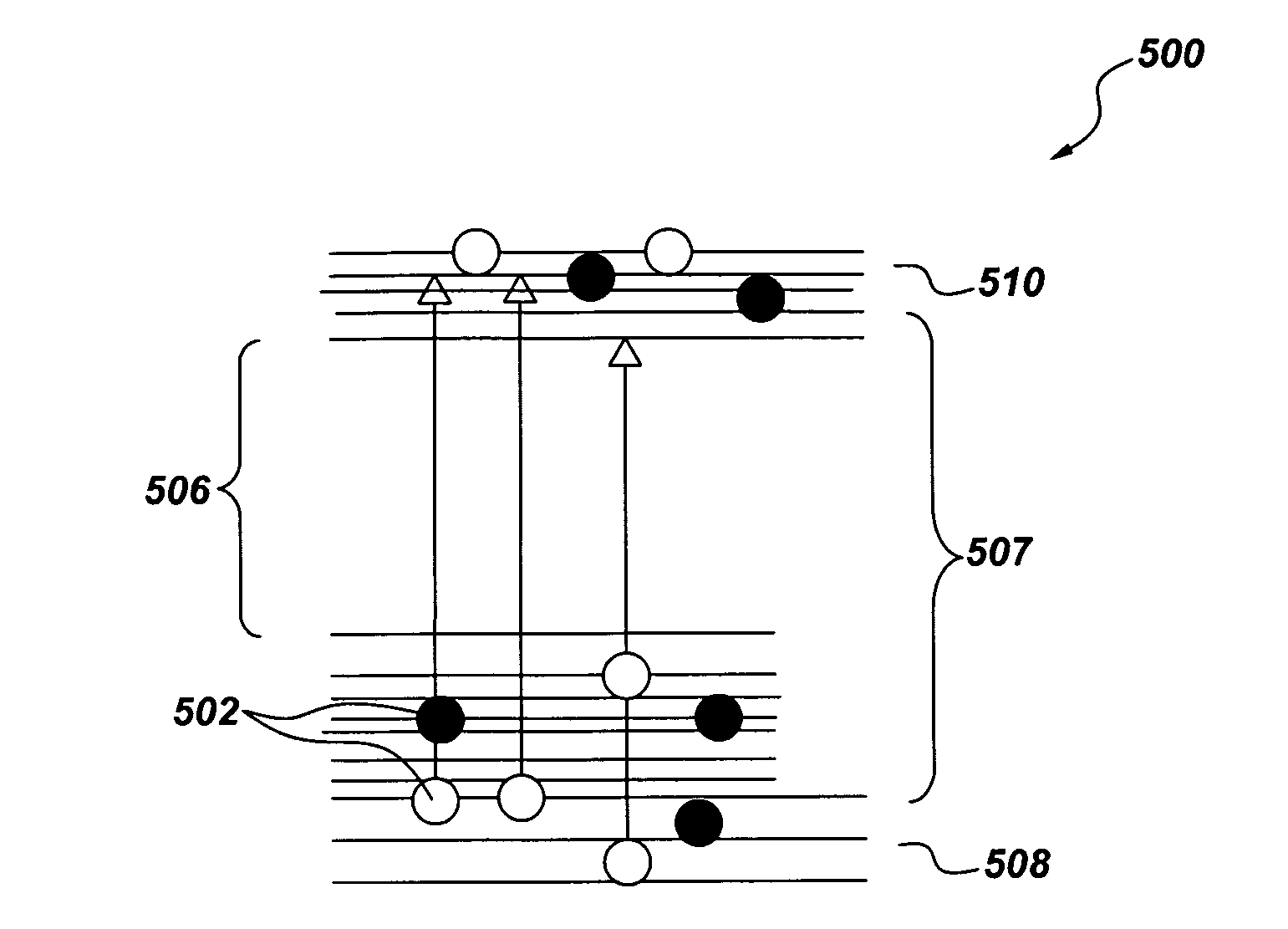
[0041]FIG. 7 is a table of various dopant and co-dopant percentages and the resulting erasure temperatures for a silica fiber based FBG sensor. As used herein, the term “erasure” refers to a change in refractive index of the grating. For a reliable operation in an elevated temperature environment, it is desirable that the grating erasure temperature exceed temperatures that are anticipated for the intended operation. A commercially available photosensitive fiber core, after being doped and co-doped in the manner described above with respect to FIG. 6, may be inscribed a UV laser energy of about 100 milliJoules per square centimeter, for example, to provide a Type I FBG inscription. As can be seen from the table, by adjusting the co-dopant atoms, combinations of atoms, and / or weight percent, the erasure temperature can likewise be adjus...


PUM

PropertyMeasurementUnit
weight percentaaaaaaaaaa

Abstract

A method of fabrication of a thermally stabilized Type I fiber Bragg grating-based temperature sensing device includes doping a fiber core material with germanium or germanium oxide for enhancing photosensitivity, co-doping the fiber core material with fluorine or chorine or for increasing a mean coordination number; and ultraviolet laser inscribing a periodic or quasiperiodic modulated refractive index structure in the fiber core using a laser energy operating at less than 1000 milliJoules per square centimeter per pulse. The resulting sensor is operable for more than 1000 hours at temperatures up to at least 550 degrees Celsius.

Description

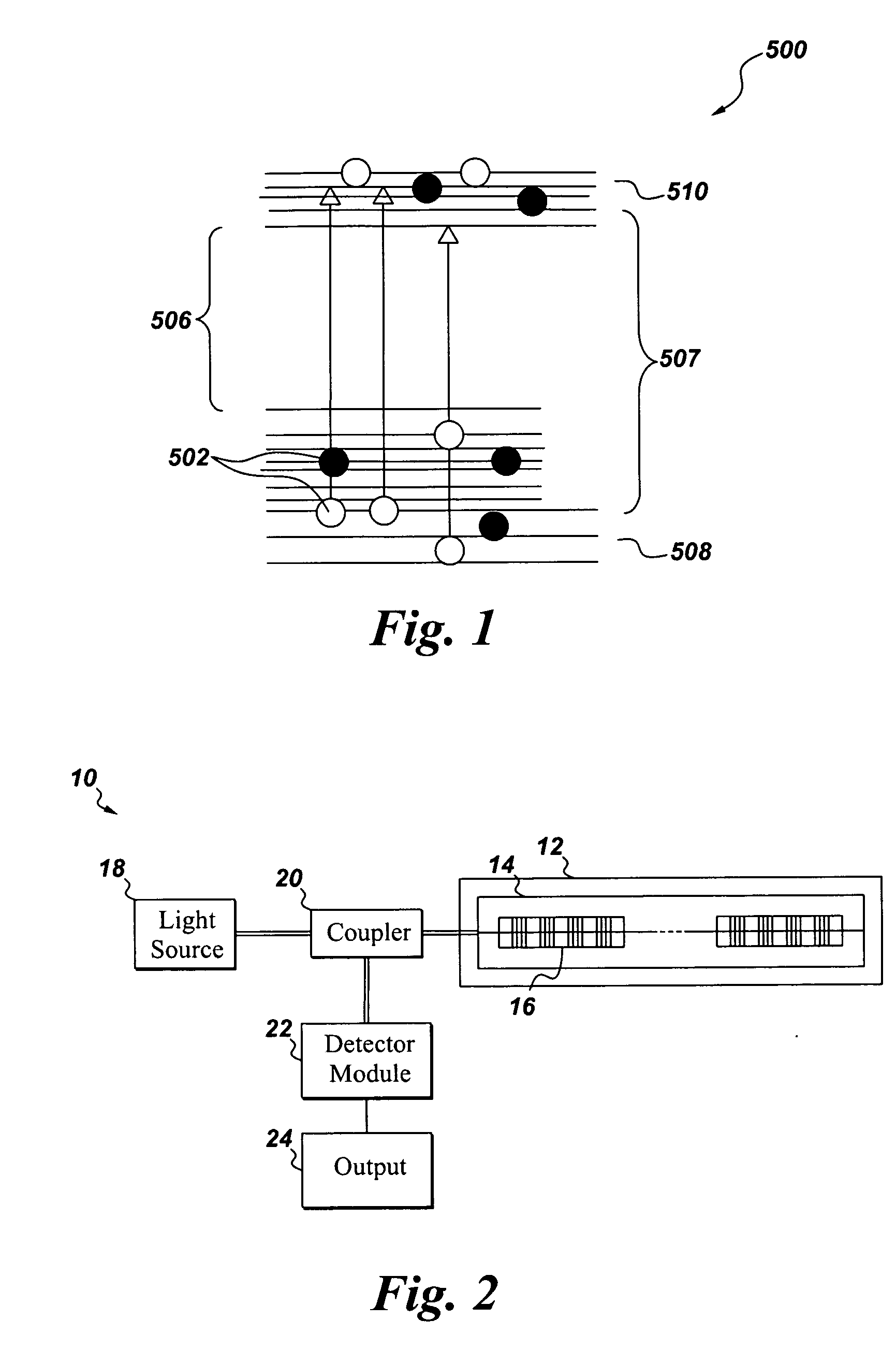
CROSS REFERENCE[0001]This application is a Continuation in Part of U.S. patent application Ser. No. 11 / 855,457, entitled “FIBER BRAGG GRATING FOR HIGH TEMPERATURE SENSING,” filed 14 Sep. 2007, which is herein incorporated by reference.BACKGROUND[0002]The invention relates generally to fiber Bragg grating based sensing devices and, more particularly, to thermally stabilized fiber Bragg grating based sensing devices that can be operated at elevated temperatures as compared with conventional fiber Bragg grating based sensing devices.[0003]In general, there are several techniques used for measurement of parameters such as temperatures. Some of the commonly used systems include thermocouples and pyrometry and blackbody measurement devices. A fiber Bragg grating (FBG) based fiberoptic temperature sensor includes a FBG that is a high quality reflector constructed in an optical fiber that reflects particular wavelengths of light and transmits other wavelengths. This is generally achieved by...

Claims


Application Information

Patent Timeline
Patent Type & Authority Applications(United States)
IPC IPC(8): G02B6/34G02B6/00B29C35/08
CPCC03B2201/08C03B2201/12C03B2201/21C03B2201/31G02B6/02204C03B2203/23G01K11/3206G02B6/02114G02B6/02138C03B2203/18
Inventor XIA, HUA
Owner AIR PROD & CHEM INC
Why Eureka
Try Eureka