Method and device for nano-imprinting

a nano-imprinting and nano-printing technology, applied in the field of nano-imprinting, can solve the problems of limited application range, mass productivity, and improved process throughput, and achieve the effects of large area, smooth release of molded objects, and large for

Inactive Publication Date: 2009-07-09
NAT INST OF ADVANCED IND SCI & TECH
View PDF3 Cites 33 Cited by
  • Summary
  • Abstract
  • Description
  • Claims
  • Application Information

AI Technical Summary

Benefits of technology

[0019]Especially in a thermal nanoimprint, if the mold release is performed after the molded body is cooled, there has been a problem in that mold release is difficult because the molded body is firmly attached with the mold due to heat contraction and thus, mold release requires a large force. There has also been a problem in that the transferred pattern is broken at the time of mold releasing by forcibly releasing the mold and the molded object, which are fixedly connected. The larger the nanoimprint area is, the more significant these problems are, and therefore, these problems should be solved in order to handle large areas. According to the abovementioned nanoimprint method and system, by using a head having a smaller pressing area than the molded range for pressing the mold onto the object to be molded gradually moving the part of the mold pressed by the head, and releasing the part of the mold that has been completed by pressing with the head, it is possible to release the mold before the effect of heat contraction of the molded object is significant, and thus the mold can be smoothly released from the molded object. It is also possible to minimize the occurrence of the problem of the pattern being broken at the time of mold releasing. Additionally, pattern transfer and mold release are nearly simultaneously performed, possibly contributing to an improvement in process throughput. The time taken between releasing the head and performing mold release should be adjusted so that the pattern transferred onto the molded body can be firmed, but preferably adjusted so that it is demolded as soon as possible after the transferred pattern is firmed.
[0020]The abovementioned nanoimprint method and system preferably optimizes the parameters for the relative moving speed between the mold and the object to be molded, the pressing load, and the temperature of the heater by sufficiently recognizing the viscoelastic properties and molding form for the resin of the workpiece material. The molding ti

Problems solved by technology

However, under current circumstances, the nanoimprint process is at a level in which a foundational process technology has been established, but there remain some important issues for practical applications, and so the application range thereof is limited under actual situations.
One of the issues is improving the process throughput.
Therefore, it is essential to improve the process throughput (time required for manufacturing a device), which is the most important issue.
At present, one process (molding fabrication process) requires a few minutes even at shortest, but generally several tens of minutes, m

Method used


Image

  • Method and device for nano-imprinting
  • Method and device for nano-imprinting
  • Method and device for nano-imprinting

Examples


Embodiment Construction

[0032]Preferred embodiments of the present invention will be described below with reference to attached drawings.

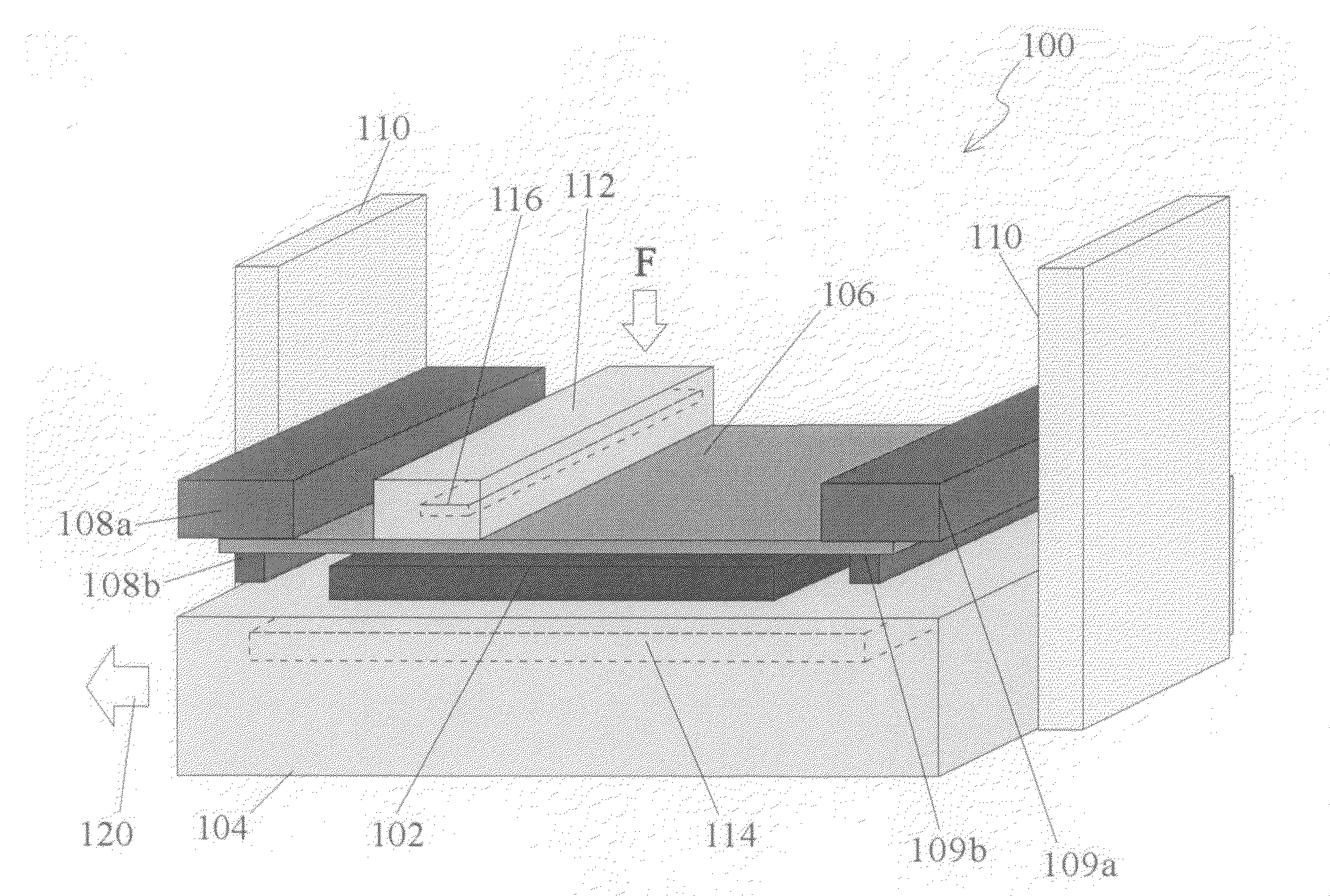
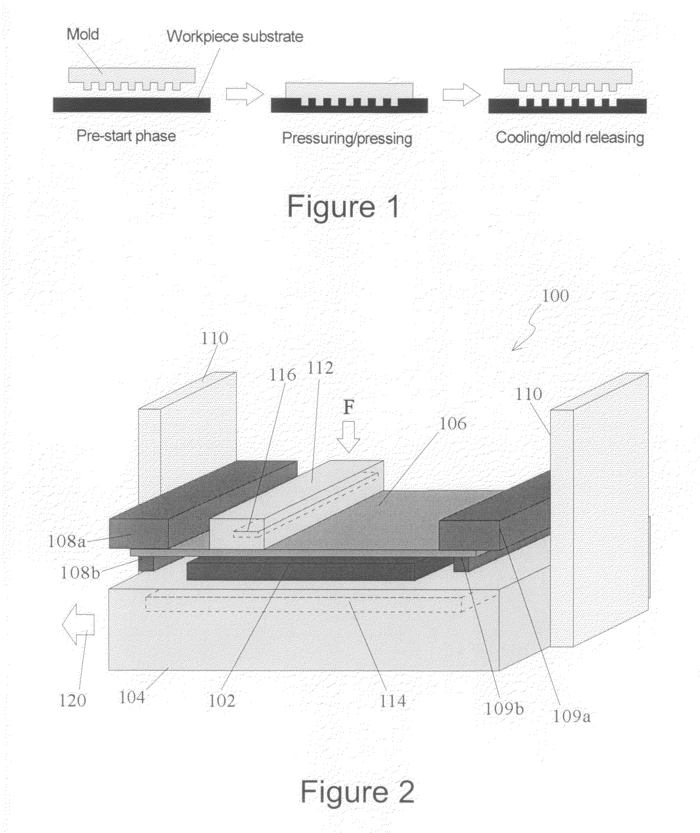
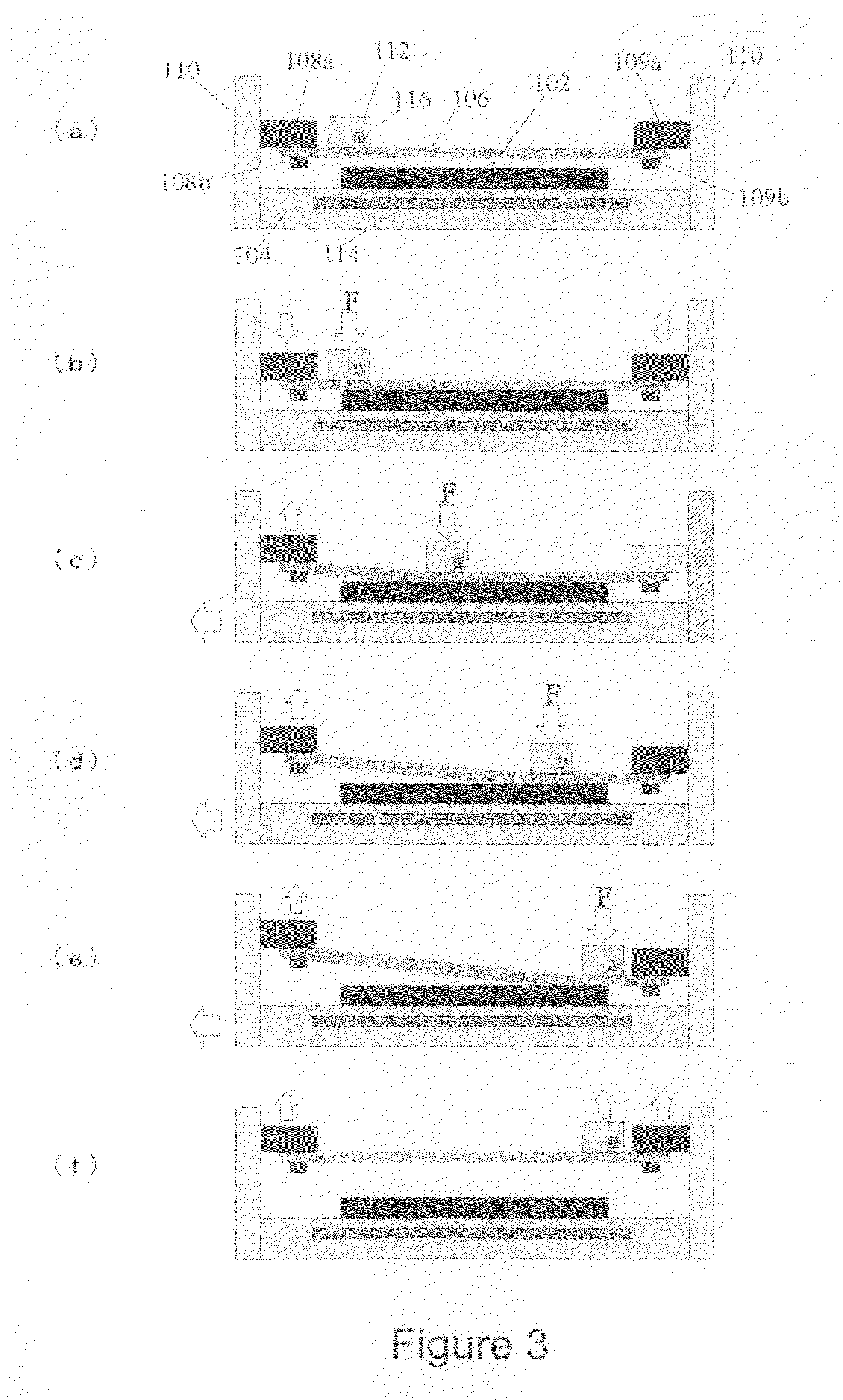
[0033]FIG. 2 is a conceptual diagram of a nanoimprint apparatus 100 according to the present invention. The nanoimprint apparatus 100 comprises a stage 104 for securing a workpiece substrate 102, a mold holding unit 108a, 108b, 109a, and 109b for securing a mold 106, a mold elevating mechanism 110 for elevating the mold 106 together with the mold holding units 108 and 109 and a head 112 for pressing the mold 106 against the workpiece material 102.

[0034]The nanoimprint apparatus 100 is capable of performing a nanoimprint on a large area by novel features provided by the present invention. In this embodiment, the nanoimprint molding area for the workpiece substrate 102 is 300×500 mm. Therefore, a large area plate mold is also used for the mold 106. Since the thickness of the mold 106 is preferably thin, considering easy mold release, the thinness of the mold is to be 200-30...


PUM

PropertyMeasurementUnit
Temperatureaaaaaaaaaa
Forceaaaaaaaaaa
Speedaaaaaaaaaa

Abstract

A nanoimprint system according to one embodiment of the present invention is a system for performing a pattern transfer onto an object to be molded by pressing a mold against the object to be molded using a head, characterized in that the head has a flat pressing surface during pressing the mold and is slid onto the mold while pressing the mold.

Description

TECHNICAL FIELD[0001]The present invention relates to nanoimprint technology, more specifically to a technology that may be employed for improving the nanoimprint process.BACKGROUND ART[0002]In recent years, nanoimprint technology has been receiving a lot of attention as a manufacturing process of ultra-fine three-dimensional nanostructures. A thermal nanoimprint process, which is one nanoimprint technology, involves heating / pressing a high precision processing form (a mold) onto a workpiece material (resin and glass), and then transferring the mold pattern onto the workpiece material. A process chart of the thermal nanoimprint process is shown in FIG. 1. This is a technology which is capable of forming a nanostructure under the very simple processes of simply heating and pressing a mold against a material.[0003]A nanoimprint process, which has been receiving attention as a promising technology for forming a 32 nm or less extra-fine line pattern in LSI lithography, has been expected...

Claims


Application Information

Patent Timeline
IPC IPC(8): B29C43/58B29C59/02B29C47/78B29C43/50
CPCB29C59/022B29C2059/023B29L2011/0016B29L2011/0091B29L2017/005G11B7/263B82Y10/00G11B5/743G11B5/82G11B5/865B81C1/0046
Inventor MAEDA, RYUTAROMEKARU, HARUTAKAGOTO, HIROSHI
Owner NAT INST OF ADVANCED IND SCI & TECH
Why Eureka
Try Eureka