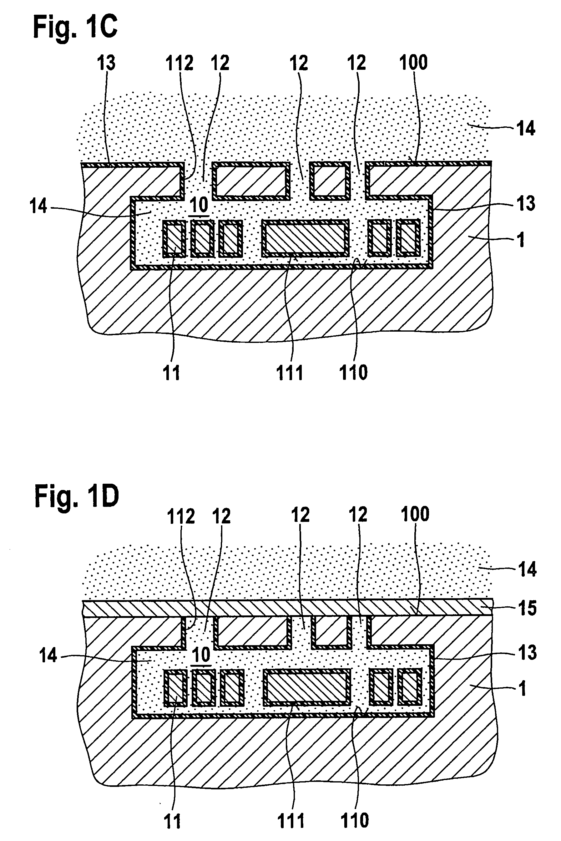
[0006]According to a first aspect of the present invention, a method is provided for sealing an opening in a substrate. The method includes the following steps: First of all, a substrate having a cavity is provided, the cavity being accessible through the opening. In addition, a fluid of a specific composition and under a specific pressure is introduced into the cavity. A sealing material is further provided that is applied on the opening and thus encloses the fluid in the cavity, in so doing, sealing material being prevented from penetrating into the cavity. The method of the present invention has the
advantage of enclosing a fluid of a specific well-defined composition and under a specific well-defined pressure in the cavity. In so doing, pressure and composition of the fluid are decoupled from the provision and the application of the sealing material on the opening. Disadvantageous ambient conditions while providing and applying the sealing material therefore do not or do not significantly influence the fluid, which is enclosed in the cavity. Thus, neither sealing material nor other—and sometimes harmful—components which are obtained upon providing and applying the sealing material penetrate into the cavity, and damage to the cavity or any structures contained in it is avoided.
[0008]According to a further specific embodiment of the present invention, the sealing material is formed by a
plasma-enhanced
chemical vapor deposition process under an
atmospheric pressure (PECVD). In a
chemical vapor deposition process, the sealing material is initially brought in the form of components to the location of the deposition, in order to form the sealing material in the same place by a chemical and / or physical transformation. In so doing, penetration of components, reaction products or sealing material itself into the cavity often results in damage to structures provided there. However, carrying out the
chemical vapor deposition according to the present invention at
atmospheric pressure advantageously prevents the
diffusion of harmful substances through the opening into the cavity. Moreover, the
atmospheric pressure essentially in the range around 1 bar, which is elevated compared to conventional deposition methods, results in an advantageous influencing of mechanical structures in the cavity. Thus, two advantages may be attained by one measure using the method of the present invention.
[0010]According to another specific embodiment of the present invention, the sealing material is applied in liquid form on the opening, so that the cavity is sealed off by solidification of the sealing material on the opening. In this context, advantageously, many customary sealing materials may be liquefied under almost any ambient conditions. The
enclosure of a well-defined fluid of specific composition under a specific pressure in the cavity thereby becomes possible.
[0012]According to a further exemplary embodiment of the present invention, the pressure of the enclosed fluid is between 500 mbar and 2 bar. On one hand, this pressure according to the exemplary embodiments and / or exemplary methods of the present invention prevents the
diffusion of harmful substances into the cavity, and on the other hand, can favorably influence the structural properties of the cavity and mechanical properties of structures located in it. Furthermore, the temperature during the application of the sealing material may be between 175° C. and 400° C. In this case, advantageously a reliable application of the sealing material, e.g., by
liquefaction, is ensured, while the temperature is not sufficient to damage components in and on the substrate.
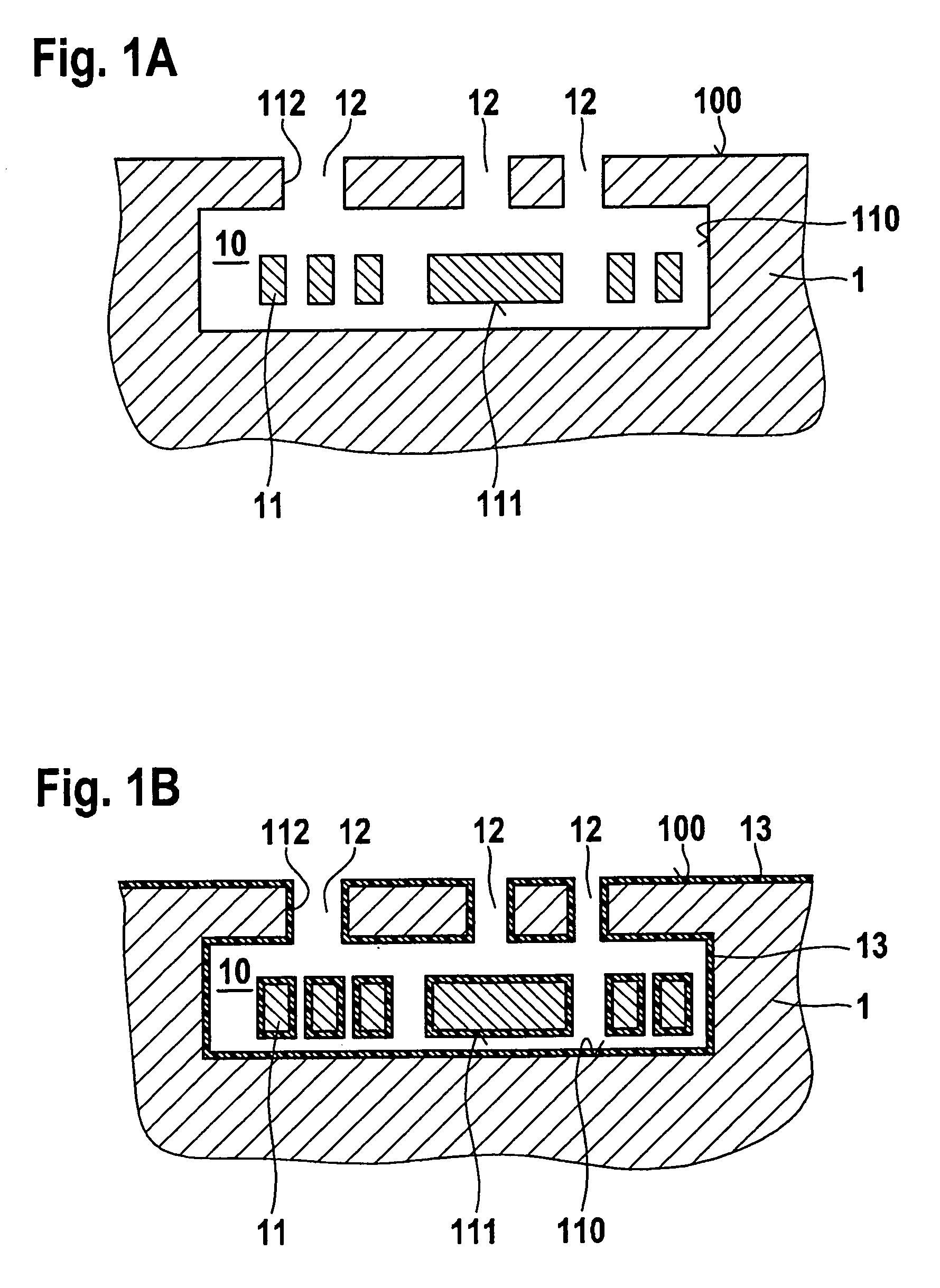
[0013]According to another exemplary embodiment of the present invention, an anti-
stiction coating is applied on an inner wall of the cavity and on a surface of the mechanical structure. This anti-
stiction coating prevents adhesion of the mechanical structure, even in the event of mechanical contact with a surface of the cavity. Since adhesion of the mechanical structure to surfaces of the cavity represents a frequent cause for unstable operation of the integrated component or even for its complete failure, the provision of the anti-
stiction coating according to the exemplary embodiments and / or exemplary methods of the present invention leads to a substantial improvement in the operation and reliability of the integrated component.
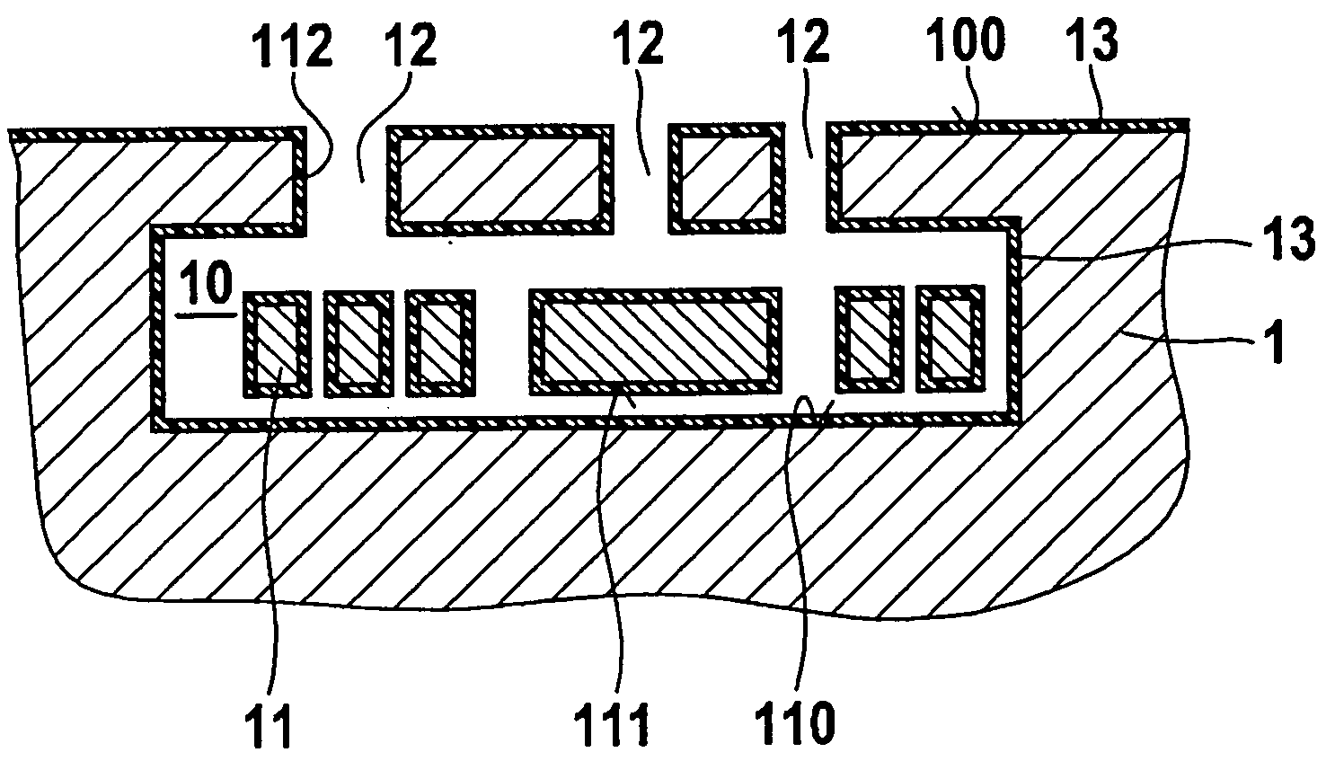
[0014]According to a second aspect of the exemplary embodiments and / or exemplary methods of the present invention, an integrated component is provided. The integrated component has a substrate having a cavity, the latter surrounding a mechanical structure. Furthermore, the cavity is filled with a fluid of a specific composition and under a specific pressure. The mechanical properties of the mechanical structure are able to be influenced considerably by the fluid. The integrated component of the exemplary embodiments and / or exemplary methods of the present invention permits a considerable influencing of the mechanical properties of the mechanical structure. Advantageously, a purposive adjustment of mechanical parameters is thus possible, like, for instance, the adjustment of the damping. At the same time, the integrated component is sealed off in reliable and stable fashion. Moreover, the production of the integrated component according to the exemplary embodiments and / or exemplary methods of the present invention is simplified substantially by a well-defined fluid of specific composition and under a specific pressure, since harmful substances are prevented from penetrating into the cavity during production. Consequently, the performance and reliability of integrated components having mechanical structures may be improved considerably.

