Optical disk apparatus and optical pickup

a technology of optical disk and optical pickup, which is applied in the field of optical disk apparatus and optical pickup, can solve the problems of degradation of heat radiation performance involved in the reduction of heat capacity of components, degradation of signal quantity, and temperature environment surrounding an ld, so as to improve the heat radiation performance of a light source without increasing the size or thickness of the apparatus

Inactive Publication Date: 2009-07-09
CANON KK
View PDF4 Cites 6 Cited by
  • Summary
  • Abstract
  • Description
  • Claims
  • Application Information

AI Technical Summary

Benefits of technology

[0021]It is, therefore, an object of the present invention to provide an optical disk apparatus which can improve the heat radiation performance of a light source without increasing the size or thickness of the apparatus.
[0024]According to the configuration of the present invention, the heat radiation performance of a light source can be improved without increasing the size or the thickness of an optical disk apparatus, compared with conventional apparatuses. With this configuration, the temperature rise of the light source can be reduced, and therefore there can be provided an optical disk apparatus in which the life time of the light source is prolonged, the degradation of the signal quality is reduced by suppressing increase in quantum noise, and the lowering of the slope efficiency is reduced.

Problems solved by technology

Further, an LD and a driver for driving an LD (hereinafter, simply referred to as “LDD”) are connected to each other on an electric circuit board, and are generally subject to an influence of an electric noise as the distance therebetween becomes larger, whereby the degradation of the signal quantity occurs.
Furthermore, the components themselves are required to be reduced in the size and thickness thereof, which causes degradation of the heat radiation performance involved in lowering in heat capacity of the components.
As described above, temperature environments surrounding an LD has become worse and worse.
However, the following problems have been posed in the above described conventional examples.
However, the heat capacity of the heat radiating component is reduced due to the size reduction of components accompanying the size reduction of the optical disk apparatus, which causes saturation of the heat quantity, with the result that the heat radiation of the LD and the LDD with the only one component cannot provide a sufficient effect.
Thereby, the power consumption of the LD and the LDD has increased and the temperature rise is also prompted.
For that reason, in the case where the technology of the first conventional example is employed while maintaining the signal quality, there has been posed a problem that a sufficient heat radiation effect cannot be obtained.
However, as described above, in general, the heat capacities of only the LD and the LDD are small, and their outer shapes themselves are also small.
Therefore, with regard to the heat generation involved in the increase in recent years of power consumption of the above-mentioned LD and LDD, a sufficient air-cooling effect may not be obtained because the respective devices have small surface areas with respect to the flowing air.
This is because a portion of the optical pickup protruding from the disk projection surface of the optical disk is increased, and therefore the air-cooling effect cannot be obtained.
As the matter of course, this is not caused when a specific cooling mechanism such as a cooling fun is provided, but enlargement in size of the apparatus may be caused.

Method used


Image

  • Optical disk apparatus and optical pickup
  • Optical disk apparatus and optical pickup
  • Optical disk apparatus and optical pickup

Examples


embodiments

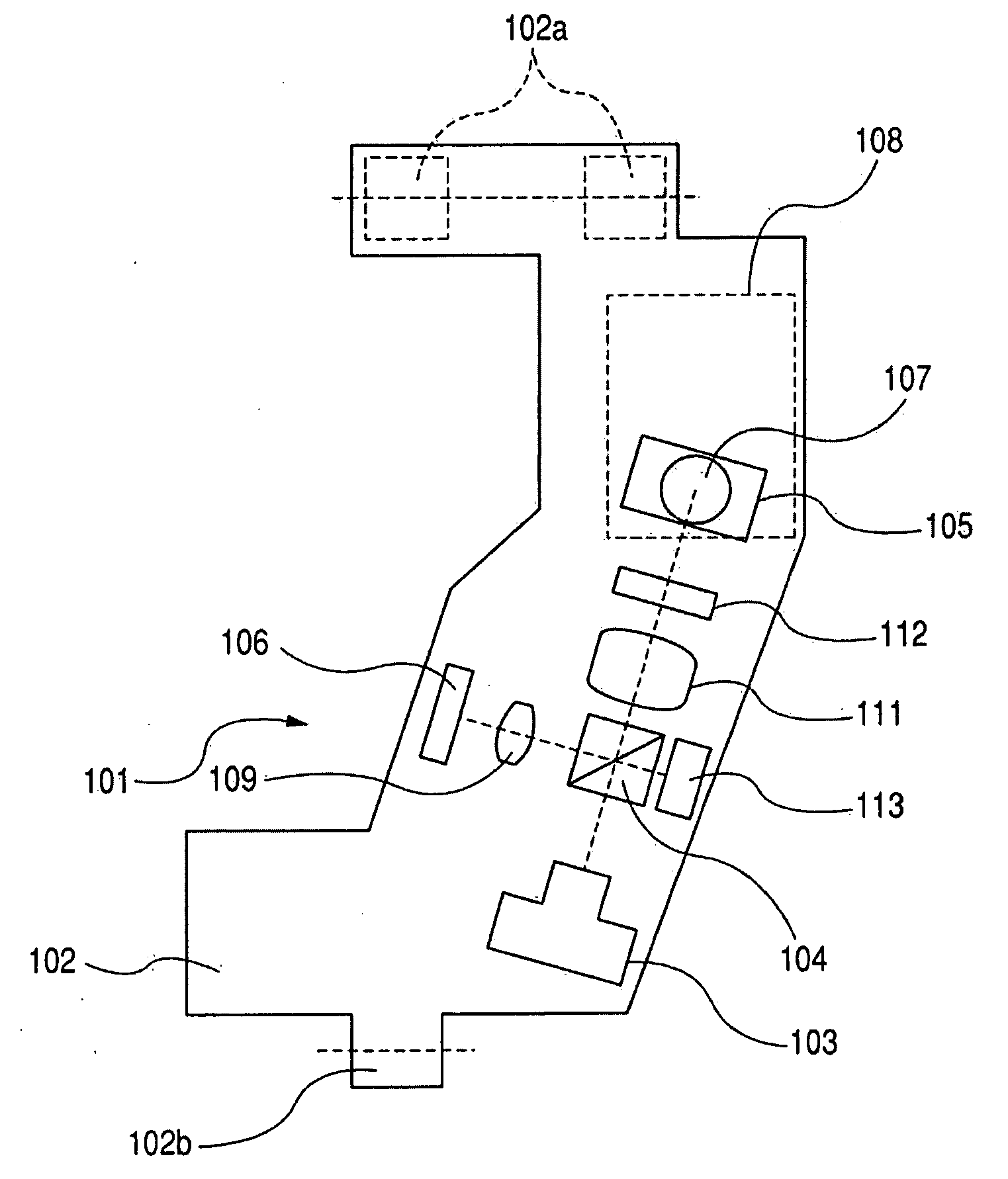
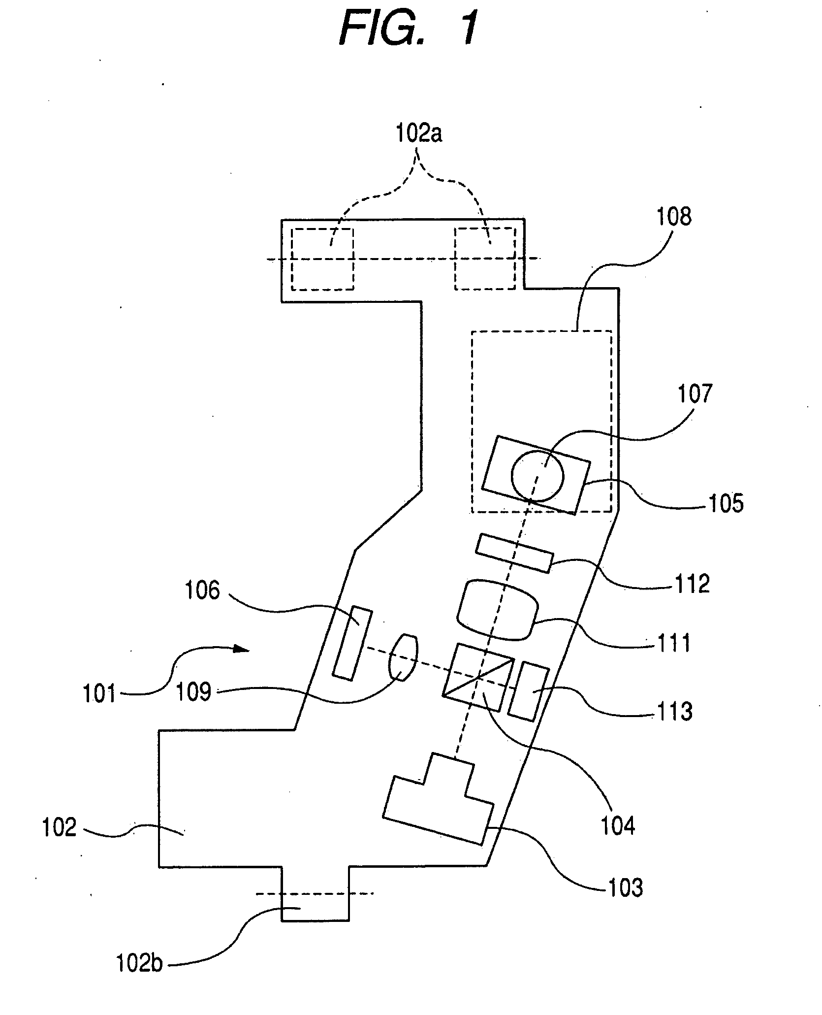
[0048]First, an optical system of an optical pickup 101 is described with reference to FIG. 1. Incidentally, FIG. 1 is a conceptual view in which the optical pickup 101 described below is simplified for description of the optical system.

[0049]An optical base 102, which is a base of the optical pickup 101, is provided with a semiconductor laser (LD) 103 serving as a light source, a polarizing beam splitter 104 serving as a splitter, a collimator 111, a quarter wavelength plate 112, a deflecting mirror 105, and an RF servo sensor 106 serving as a light receiving device. Furthermore, there are disposed an objective lens actuator 108 which supports an objective lens 107 so as to be capable of biaxially driving the objective lens 107 in a focusing direction and a tracking direction with respect to recording tracks of an optical disk 110 serving as a disk-shaped recording medium, a sensor lens 109, and a monitor sensor 113. Incidentally, as the structure of the objective lens actuator 108...


PUM

PropertyMeasurementUnit
diameteraaaaaaaaaa
distanceaaaaaaaaaa
distanceaaaaaaaaaa

Abstract

Provided is an optical disk apparatus that suppresses shortening of the life time of a light source, degradation of the signal quality involved in an increase in quantum noise, and lowering of the slope efficiency, which are caused by a temperature increase of the light source by a lowering in the heat radiation performance of the light source due to size reduction or thickness reduction of the apparatus. As a specific structure, the optical disk apparatus includes an optical pickup including: a light source; a light source drive circuit; an optical base housing an optical system for guiding light emitted from the light source to a disk-shaped recording medium; a first heat radiation member connected to the light source; and a second heat radiation member connected to the light source drive circuit.

Description

BACKGROUND OF THE INVENTION[0001]1. Field of the Invention[0002]The present invention relates to a semiconductor laser in an information recording / reproducing apparatus using an optical disk, and to countermeasure for heat radiation for a drive circuit of a semiconductor laser.[0003]2. Description of the Related Art[0004]A semiconductor laser (hereinafter, simply referred to as “LD”), which is a light source of an optical disk apparatus, is well known for posing various problems due to temperature rise, such as shortening of life time, degradation of signal quality involved in an increase of quantum noise, lowering of a slope efficiency showing a relation between a drive current and an emission efficiency.[0005]Further, an LD and a driver for driving an LD (hereinafter, simply referred to as “LDD”) are connected to each other on an electric circuit board, and are generally subject to an influence of an electric noise as the distance therebetween becomes larger, whereby the degradati...

Claims


Application Information

Patent Timeline
Patent Type & Authority Applications(United States)
IPC IPC(8): G11B7/00
CPCG11B7/125G11B7/08582
Inventor TORII, SHINNOSUKE
Owner CANON KK
Why Eureka
Try Eureka