
Multiple-mode modulator to process baseband signals

Active Publication Date: 2009-07-09
PANASONIC CORP
View PDF6 Cites 46 Cited by
  • Summary
  • Abstract
  • Description
  • Claims
  • Application Information

AI Technical Summary

Benefits of technology

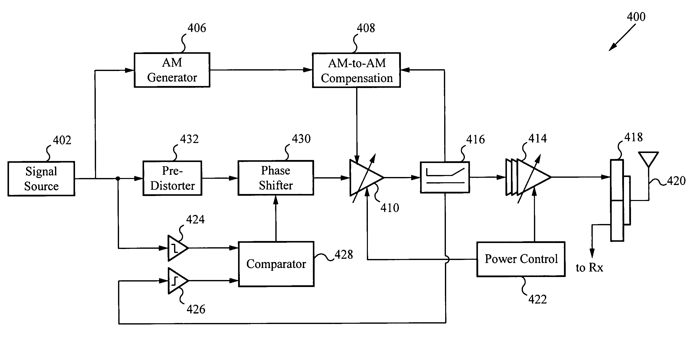
[0027]In some embodiments, the multiple-mode modulator is configured similarly to a direct conversion quadrature modulator with an infusion of an AM compensation feedback loop and a PM compensation feedback loop from the large signal polar modulator to improve the PA efficiency. This multiple-mode architecture provides similar PA efficiencies as the polar architecture by operating the PA into the compressed region. In addition, the multiple-mode architecture processes the signal partially in the I / Q domain and partially in the polar domain. Consequently, bandwidth expansion is much less for this architecture. By processing the signal in the mixed form of the I / Q domain and the polar domain, this architecture is easily applicable to other higher data rate standards, for example 802.11x and WiMAX.

Problems solved by technology

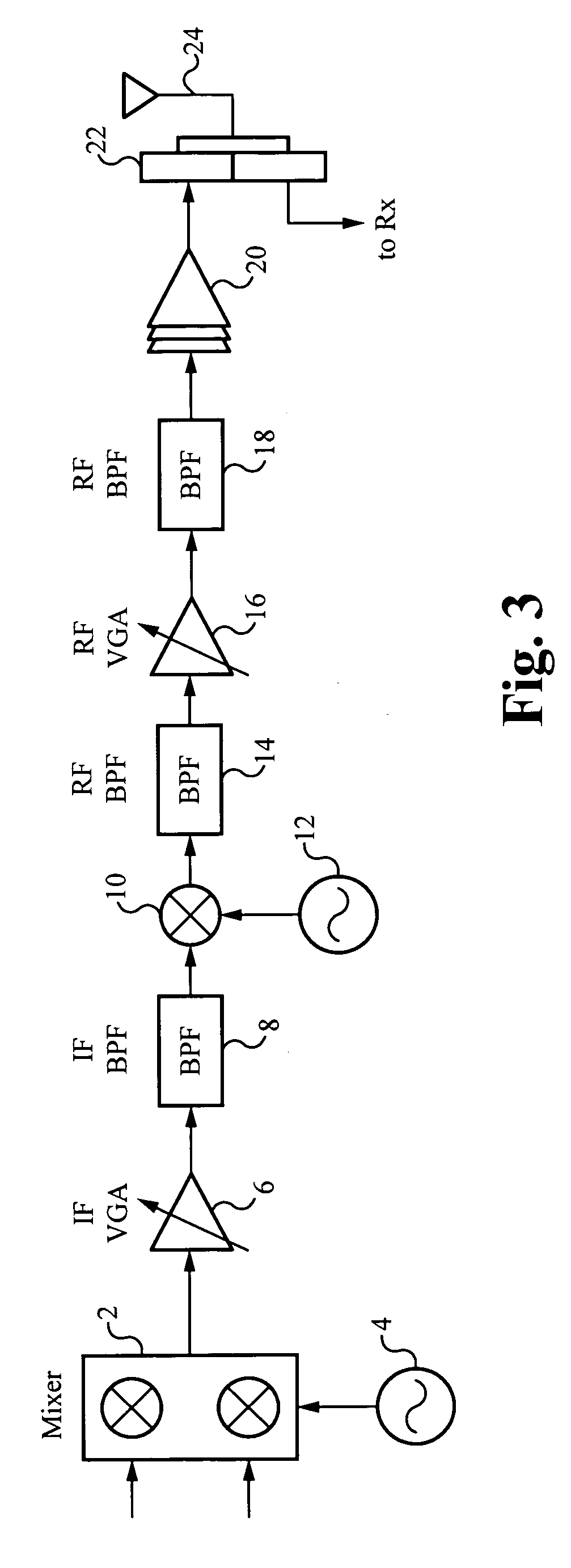
The super-heterodyne quadrature modulator requires complicated circuitry.
Usually, the final stage PA 20 efficiency is poor especially with signals which have high Peak-to-Average Ratio (PAR).
Similarly to the super-heterodyne quadrature modulator, the direct conversion quadrature modulator also suffers from poor PA efficiency.
This will further reduce the PA efficiency of the direct conversion quadrature modulator.
However, for several applications, direct conversion quadrature modulator offers an effective compromise of performance for power consumption and circuit complexity.
However, the output power of the preliminary stage amplifier 70 is not sufficient, thus requiring the final stage PA 72.
As a result, the final stage PA efficiency is poor.
However, the small signal polar modulator does not reach the same level of PA efficiency achieved by a large signal polar modulator.
Therefore, the small signal polar modulator suffers from the expanded bandwidth problem, which results in added circuit complexity and current consumption.
However, there are doubts about the possibilities of applying this architecture to wider bandwidth modulations and standards with large power control ranges.
It is very difficult to implement the traditional translational loop to handle such a bandwidth while keeping the in-band noise low.
It is questionable as to whether or not the large signal polar architecture with closed-loop feedback can be applied to CDMA standards with reasonable circuit complexity and current consumption.
This imposes significant design challenges to expand polar architectures to much higher data rate transmission standards, for example 802.11× or WiMAX.
This poses significant design challenges to the TxVCO design.
Another common concern for polar implementation is an AM signal-to-PM signal alignment problem.
The analog components on the AM and PM modulation paths are not as stable as digital components and are subject to temperature variation and aging.
With the increasing demand for higher data rates, which provides for more feature rich applications, GSM can no longer fulfill the needs of mobile device users.

Method used


Image

  • Multiple-mode modulator to process baseband signals
  • Multiple-mode modulator to process baseband signals
  • Multiple-mode modulator to process baseband signals

Examples


Embodiment Construction

[0047]Embodiments of the present invention are directed to multiple-mode modulators. Those of ordinary skill in the art will realize that the following detailed description of the present invention is illustrative only and is not intended to be in any way limiting. Other embodiments of the present invention will readily suggest themselves to such skilled persons having the benefit of this disclosure.

[0048]Reference will now be made in detail to implementations of the present invention as illustrated in the accompanying drawings. The same reference indicators will be used throughout the drawings and the following detailed description to refer to the same or like parts. In the interest of clarity, not all of the routine features of the implementations described herein are shown and described. It will, of course, be appreciated that in the development of any such actual implementation, numerous implementation-specific decisions must be made in order to achieve the developer's specific ...


PUM


Abstract

A multiple-mode modulator is configured similarly to a direct conversion quadrature modulator with an infusion of an amplitude modulation signal path from a large signal polar modulator to improve the power amplifier efficiency. The multiple-mode modulator also includes a radio frequency signal path. The multiple-mode modulator is configured to receive a baseband signal, convert the baseband signal to a radio frequency (RF) signal, and to process the RF signal according to either a polar mode or a quadrature mode, depending on a time-varying input voltage of the RF signal. When the power amplifier operates in the linear region, the RF signal is processed according to the quadrature mode. When the power amplifier operates in the compressed region, the RF signal is processed according to the polar mode. The multiple-mode modulator can be configured according to a small signal polar architecture or a large signal polar architecture, having either an open-loop or closed-loop configuration.

Description

FIELD OF THE INVENTION[0001]The present invention relates to modulators. More particularly, the present invention relates to a multiple-mode modulator to process baseband signals.BACKGROUND OF THE INVENTION[0002]Modulators are used extensively in the wireless communications industry. Using a typical modulator, an input baseband signal is modulated, amplified, and transmitted as a radio frequency (RF) signal. To generate the RF signal according to quadrature modulation, an input signal is first processed by a baseband processor to generate an in-phase (I) signal component and a quadrature (Q) signal component. The I and Q (I / Q) signal components are processed and mixed to form the RF signal.[0003]An RF signal can also be generated using polar modulation, where the analog I / Q signal is converted to an amplitude modulation (AM) signal component and a phase modulation (PM) signal component. In a polar modulator, the AM signal and the PM signal are processed separately before being combi...

Claims


Application Information

Patent Timeline
IPC IPC(8): H04B1/02
CPCH04B1/0483
Inventor LIANG, PAUL CHENG-POTAKINAMI, KOJIWALSWORTH, RICHARD
Owner PANASONIC CORP
Learn More