Process for reforming hydrocarbons

a hydrocarbon and catalyst technology, applied in the field of gas rich production process, can solve the problem of metal parts falling within the prohibitive range of metal dusting temperature, and achieve the effect of increasing the propensity for reforming catalys

Inactive Publication Date: 2009-07-23
HALDOR TOPSOE AS
View PDF7 Cites 44 Cited by
  • Summary
  • Abstract
  • Description
  • Claims
  • Application Information

AI Technical Summary

Benefits of technology

[0027]In yet another embodiment of the process, the invention further comprises passing the hydrocarbon feedstock through an adiabatic pre-reforming stage prior to conducting said first reforming stage in the radiant furnace. The provision of a pre-reforming stage in the form of adiabatic reforming by passage through a fixed bed of pre-reforming catalyst, such as a nickel based catalyst, enables removal of any traces of sulphur in the hydrocarbon feed and as a result poisoning of downstream catalyst in the radiant furnace and other downstream processes such as CO-shift conversion is eliminated. In partic

Problems solved by technology

Particularly, in such known arrangements with the heat exchange reformer in parallel or series with the radiant furnace and/or autothermal reformer, a portion of the heat exchange reformer will be relatively cold and therefore be subjected to metal du

Method used


Image

  • Process for reforming hydrocarbons
  • Process for reforming hydrocarbons

Examples


example

Example 1

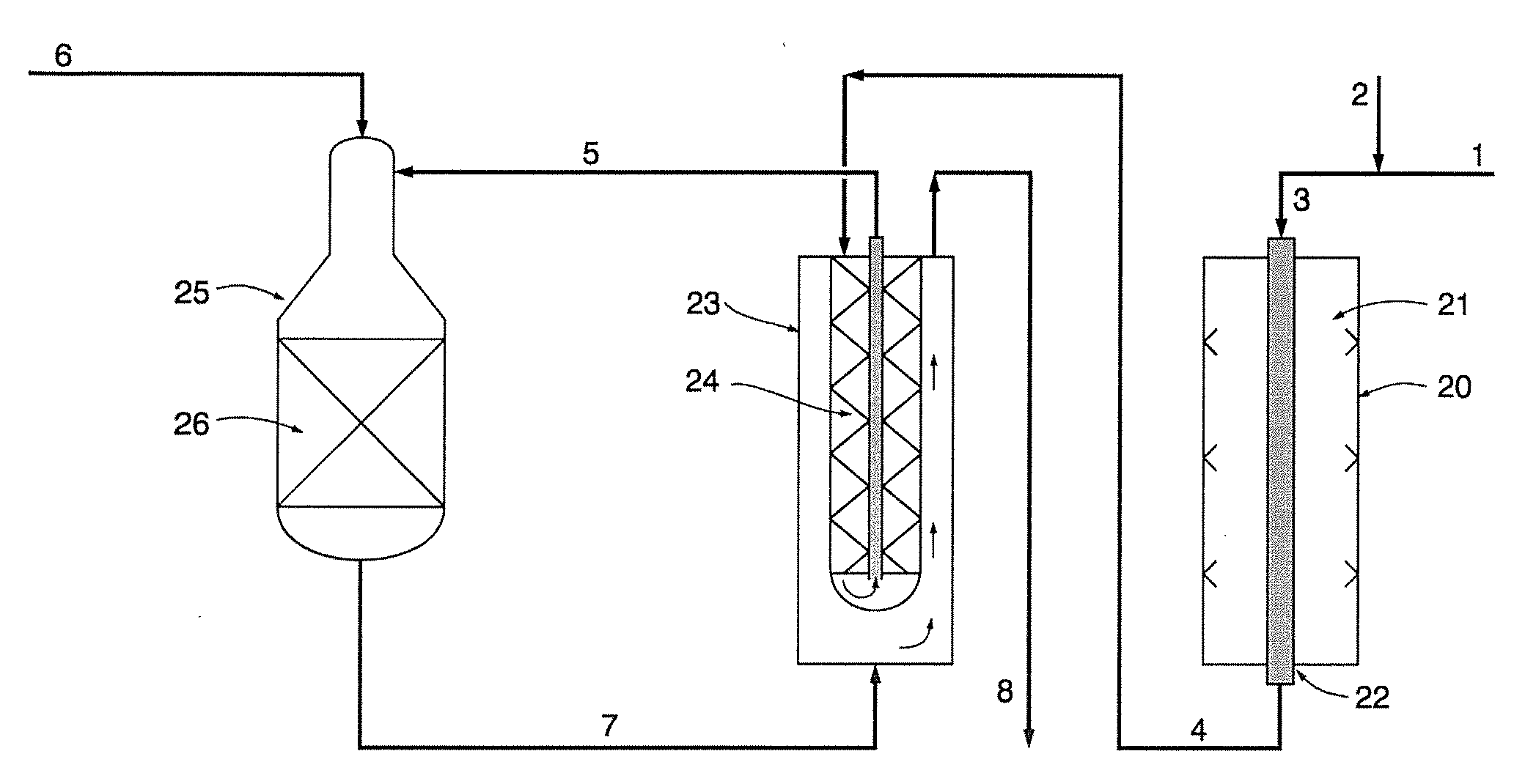
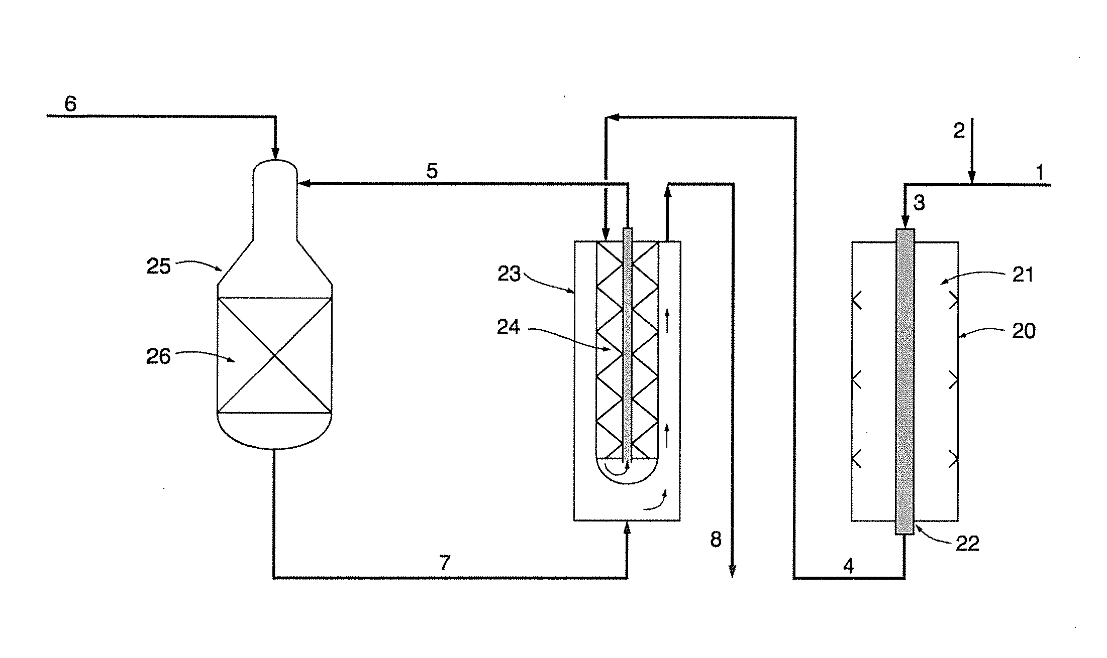
[0030]Table 1 shows the wall temperatures of a 9 m long catalyst tube of the bayonet type containing an inner tube, outer tube and sleeve as described above in a heat exchange reformer treating 209000 Nm3 / h of process gas from the radiant furnace and operating at about 35 bar g for a process according to a layout as depicted in the accompanying FIGURE. The S / C-ratio in the hydrocarbon mixture-steam entering the radiant furnace is 2.5 and process air with 21 vol % oxygen is injected to the ATR. The outlet temperature of the gas from the radiant furnace is 750° C. and the temperature of the effluent gas from the ATR is 1027° C. At the bottom of the catalyst tube, the wall temperature is 949° C. and as the synthesis gas from the ATR cools on its passage through the heat exchange reformer the wall temperature of the catalyst tube decreases. At the top of the tube, where the synthesis gas leaves the heat exchange reactor, the synthesis gas temperature has decreased to 776° C., w...


PUM


Abstract

The invention relates to a process for the production of synthesis gas from a hydrocarbon feedstock, wherein the entire hydrocarbon feed is passed through a radiant furnace, heat exchanger reformer and autothermal reformer in a series arrangement, and in which effluent gas from the autothermal reformer is used as heat source for the reforming reactions occurring in the heat exchange reformer.

Description

FIELD OF THE INVENTION[0001]The present invention relates to a process for production of gas rich in hydrogen, particularly synthesis gas for the production of ammonia, methanol, dimethyl ether (DME), hydrogen and hydrocarbons by Fischer-Tropsch synthesis. More particularly, the invention relates to the production of synthesis gas by means of a series arrangement of radiant furnace reforming, heat exchange reforming and autothermal reforming stages, in which the heat required for the reactions in the heat exchange reforming stage is provided by hot effluent synthesis gas from the autothermal reforming stage.BACKGROUND OF THE INVENTION[0002]The use of a product stream of reformed gas as a source of heat in heat exchange reforming is known in the art. Thus, EP-A-0033128 and EP-A-0334540 deal with parallel arrangements, in which a hydrocarbon feed is introduced in parallel to a radiant furnace and heat exchange reformer. The partially reformed gas from the radiant furnace is then used ...

Claims


Application Information

Patent Timeline
IPC IPC(8): C01B3/38
CPCC01B3/382C01B2203/0233C01B2203/0244C01B2203/143C01B2203/0816C01B2203/0833C01B2203/1241C01B2203/0283
Inventor HAN, PAT A.
Owner HALDOR TOPSOE AS
Why Eureka
Try Eureka