Power transmission circuit

Inactive Publication Date: 2009-07-23
PANASONIC LIQUID CRYSTAL DISPLAY CO LTD +1
View PDF18 Cites 26 Cited by
  • Summary
  • Abstract
  • Description
  • Claims
  • Application Information

AI Technical Summary

Benefits of technology

[0011]An impedance between the power supply and the load generated by capacitive coupling (electrostatic capacitance) is normally a value which cannot be neglected as compared with a variation in the load impedance. A load voltage also varies depending on the variation in load impedance. When a constant voltage circuit which is the shunt regulator is inserted at a subsequent stage of the rectifier, the variation in load voltage is suppressed. When inductors are inserted in series with capacitors (capacitances) serving as capacitive coupling to construct resonant circuits, thereby setting a frequency of an alternating current power signal to a vicinity of a resonance frequency, the impedance between the power supply and the load is reduced.
[0012]When a full-wave rectification circuit (diode bridge) is a

Problems solved by technology

Therefore, a rectifying device located on a display panel side is required to have high performance (response speed), and hence it is difficult to realize such a system by TFTs provided in the display panel.
In a case of the electromagnetic induction, it is

Method used


Image

  • Power transmission circuit
  • Power transmission circuit
  • Power transmission circuit

Examples


embodiment 1

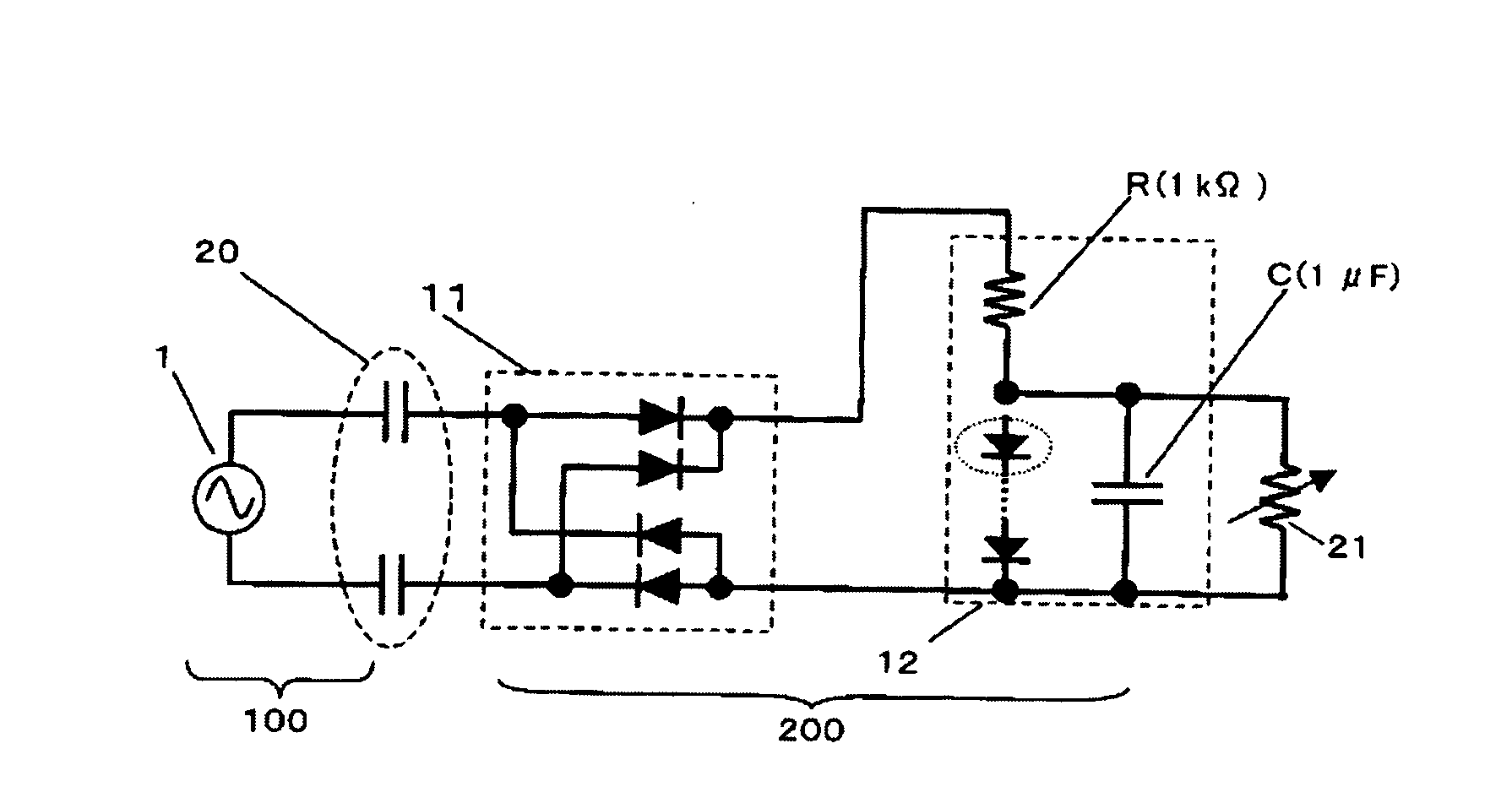
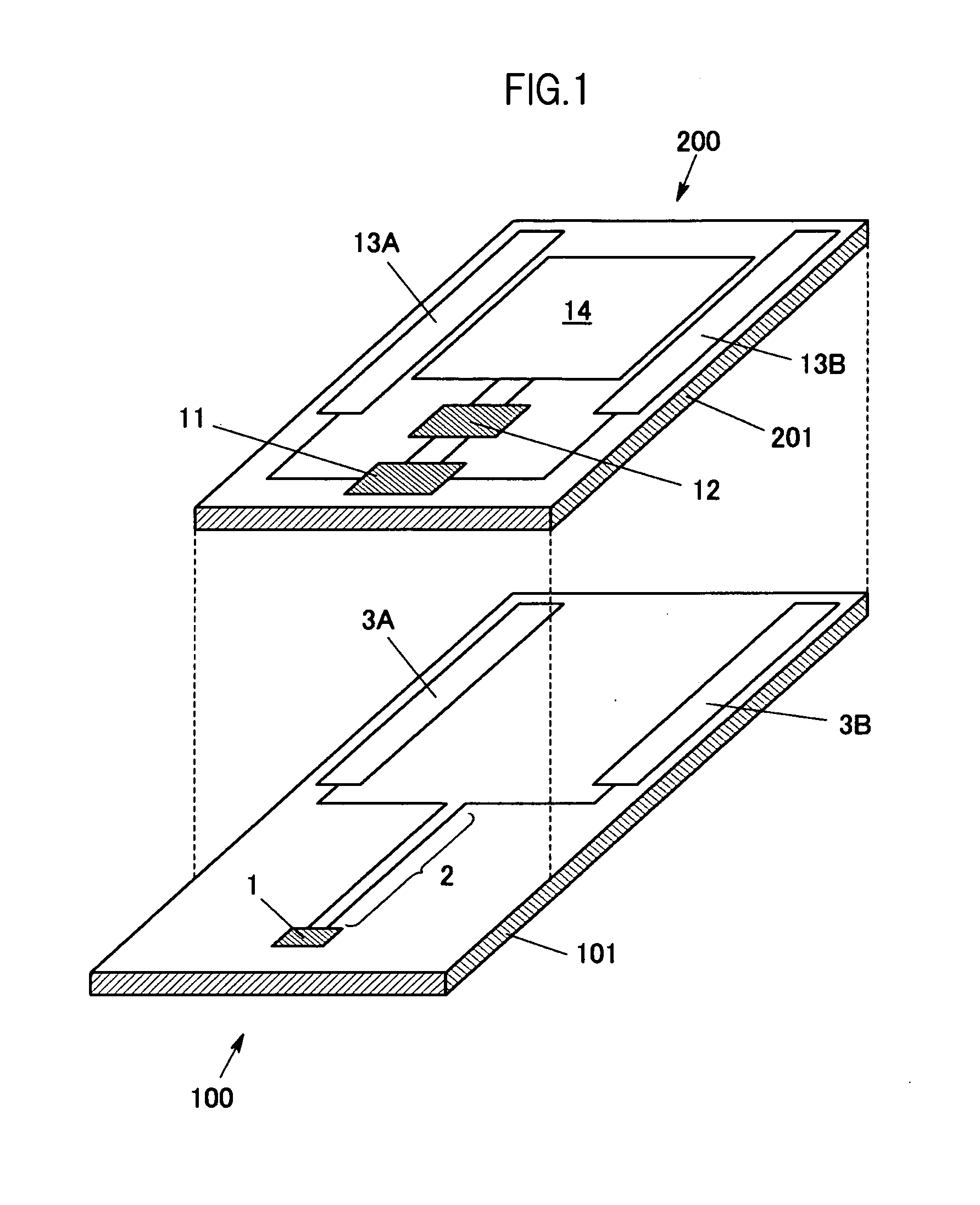
[0032]FIG. 1 is a developed explanatory perspective view illustrating a structure of a display panel according to Embodiment 1 of the present invention, to which a transmitting board for transmitting a display power signal through a non-contact transmission and a power receiving circuit for realizing reception are applied. A liquid crystal display panel including an active matrix board is assumed as an example of a power-supplied side. The display panel normally includes a panel circuit board on which circuit elements related to a display function are integrated, a panel opposite board, and a liquid crystal portion sandwiched between both the boards. In FIG. 1, the panel opposite board and the liquid crystal portion of the display panel are not illustrated, and the panel circuit board is illustrated as a receiving board 200. The receiving board 200 includes a display region in which a plurality of pixels are arranged in matrix and a display drive circuit, which are collectively deno...

embodiment 2

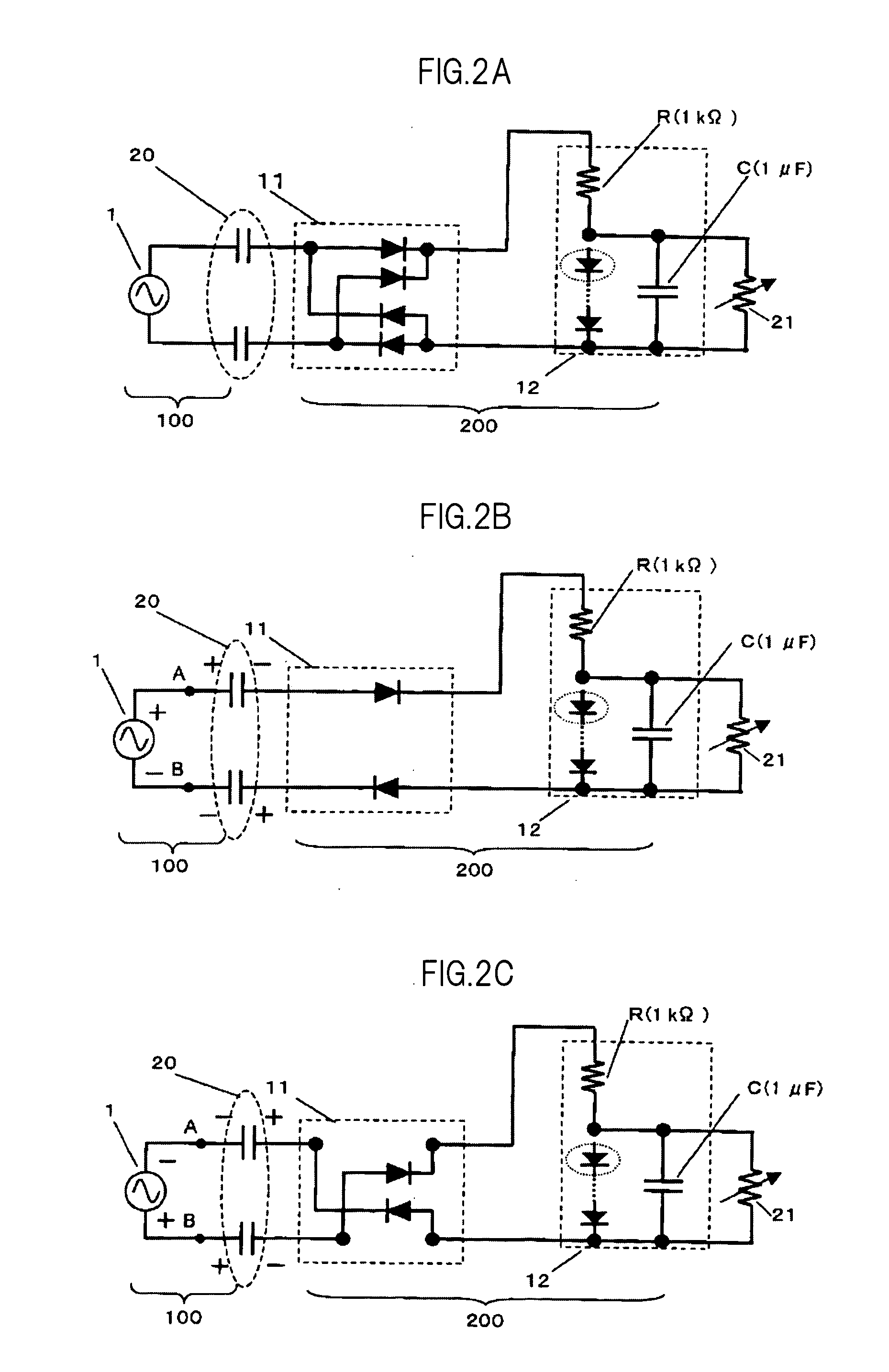
[0040]FIG. 4A is a developed explanatory perspective view illustrating a structure of a power transmission in which coupling capacitors are connected in series with inductors, according to Embodiment 2 of the present invention. FIG. 4B is an explanatory circuit diagram illustrating the structure of FIG. 4A. As in Embodiment 1, the liquid crystal display panel is described as an example. A series resonant circuit comprises each of the coupling capacitors which configure a capacitive coupling 20 and corresponding each of inductors 4 connected in series with the coupling capacitors. When the alternating current signal is transmitted at a resonance frequency, an alternating current impedance at the capacitive coupling 20 may be reduced. In FIG. 4B, the remaining structure is identical to that of the circuit illustrated in FIG. 2A.

[0041]Specifically, when an additional inductance (one side) is expressed by L and a coupling capacitance (same side) is expressed by C, a resonance frequency ...

embodiment 3

[0045]FIG. 7A is an explanatory diagram illustrating the rectifier 11 and the constant voltage circuit 12 which are described in Embodiment 3 of the present invention. The rectifier described in Embodiment 1 is constructed with a double voltage rectification system (voltage doubler rectifier).

[0046]FIGS. 7B, 7C, and 7D are explanatory diagrams illustrating an operation of the circuits of FIG. 7A. The advantage of the circuit according to Embodiment 3 is that power may be transmitted at a half alternating current voltage (effective voltage) as compared with Embodiment 1. The operation of the circuits illustrated in FIG. 7A is described with reference to FIGS. 7B to 7D. As illustrated in FIG. 7B, when the terminal A is higher in electric potential than the terminal B, the coupling capacitors of the capacitive coupling 20 are charged with charges of signs illustrated in FIG. 7B as in Embodiment 1. Then, when the terminal A is lower in electric potential than the terminal B, a current d...


PUM


Abstract

Provided is a capacitor coupling type power transmission circuit in which a variation in receiving side voltage due to a variation in capacitance is suppressed to prevent an influence on a variation in load current in a display panel. An insulating board of the display panel is sandwiched by capacitive coupling electrodes formed on each of a transmitting side board and a board of the display panel, thereby forming capacitors. A non-contact transmission is performed by the capacitors. An alternating current voltage signal obtained by electrodes on a display panel side is rectified by a rectifier including diodes. A constant voltage circuit which is a shunt regulator including a diode array in which a resistor and a plurality of diodes are connected in series is provided to maintain a stabilized voltage irrespective of a variation in load in the display panel.

Description

CROSS-REFERENCE TO RELATED APPLICATION[0001]The present application claims priority from Japanese application JP2008-010075 filed on Jan. 21, 2008, the content of which is hereby incorporated by reference into this application.BACKGROUND OF THE INVENTION[0002]1. Field of the Invention[0003]The present invention relates to a power transmission circuit for transmitting power from a board to another board in a non-contact manner, and is suitable for a circuit for transmitting power to a flat type display panel such as a liquid crystal display panel in an electrically non-contact manner.[0004]2. Description of the Related Art[0005]If power may be transmitted to a flat type display panel including a liquid crystal display panel in a non-contact manner without using a mechanical means such as a cable, a reduction in the number of parts such as wiring materials attached to the display panel, a reduction in mounting cost of the display panel, and a simplification of a manufacturing process ...

Claims


Application Information

Patent Timeline
IPC IPC(8): G09G5/00
CPCG02F1/13452G09G3/2096H02M7/06G09G2330/02H02J5/005G09G3/3611H02J50/12H02M7/05
Inventor FURUTA, FUTOSHIKAGEYAMA, HIROSHITAKEI, KEN
Owner PANASONIC LIQUID CRYSTAL DISPLAY CO LTD
Why Eureka
Try Eureka