
Method and apparatus for producing arbitrary pulsetrains from a harmonic fiber laser

a harmonic fiber laser and pulsetrain technology, applied in the direction of laser details, instruments, light demodulation, etc., can solve the problems of amplifier lasing, damage to optical components, and the inversion of the gain medium will increase dramatically on the timescale of the gain relaxation ra

Active Publication Date: 2009-07-23
LADARSYST INC
View PDF7 Cites 65 Cited by
  • Summary
  • Abstract
  • Description
  • Claims
  • Application Information

AI Technical Summary

Benefits of technology

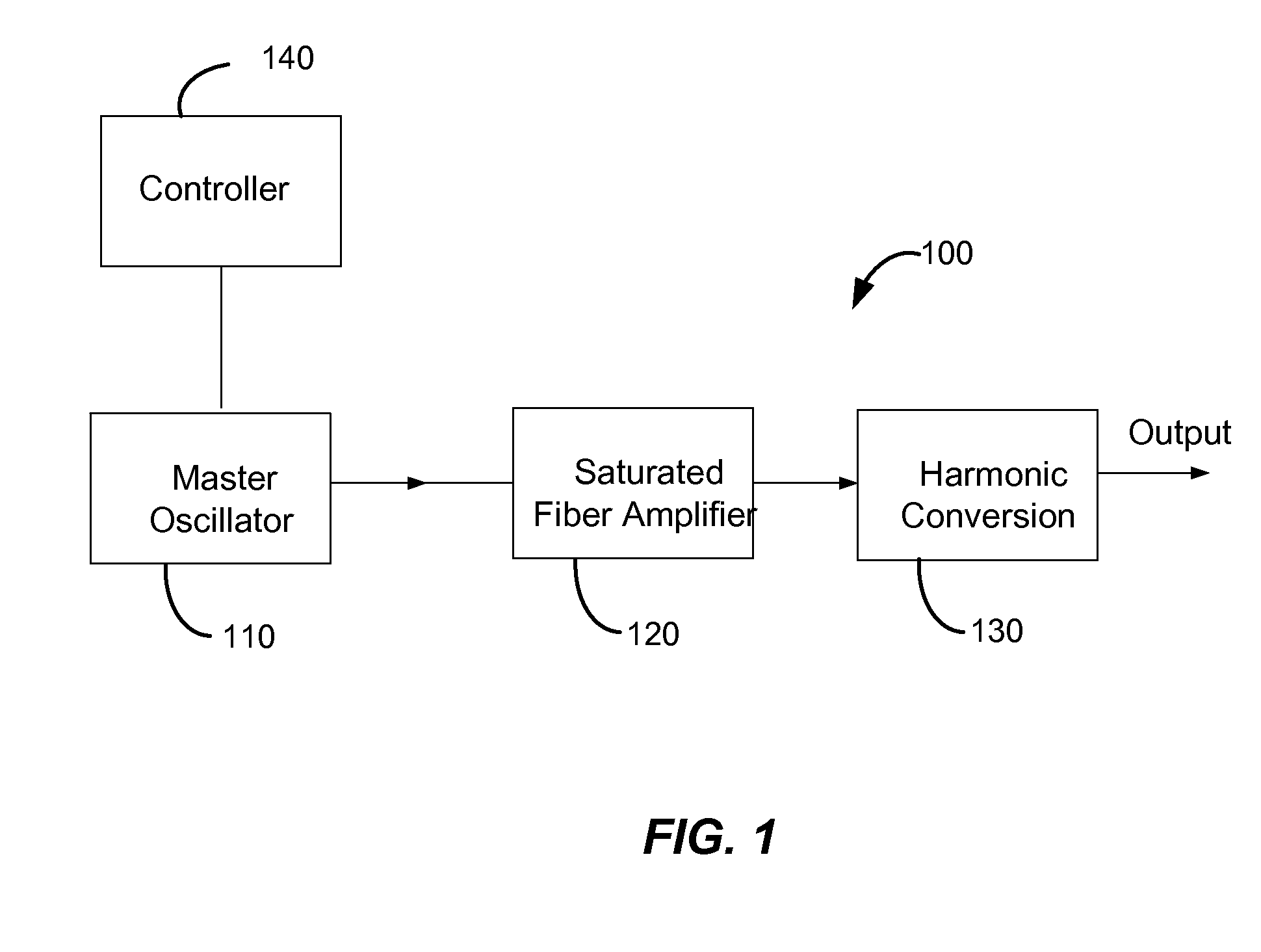
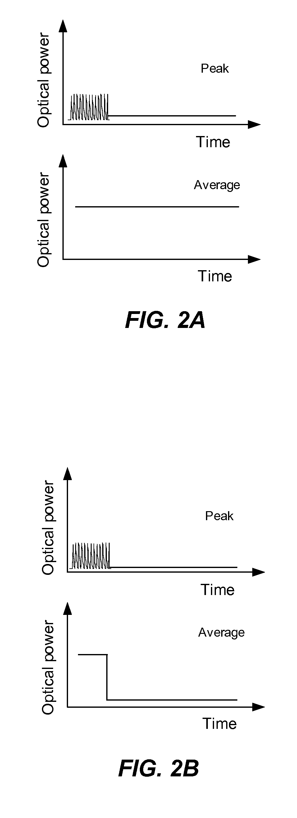
[0009]The novel apparatus and method described herein provides arbitrary modulation of frequency-converted laser pulses from a master oscillator / fiber amplifier laser system that operates with high efficiency and without self-damage. The system does not require a shuttered output or modifications to the amplifier pump power in order to turn on and off the harmonic emission from the laser system. In an embodiment, when a zero harmonic laser output is desired from the system, the master oscillator alters its emission by a means to supply enough average power to maintain fiber power amplifier saturation while the harmonic conversion stage is brought to very low efficiency. By designing the nonlinear optical conversion stage to work in concert with the master oscillator, embodiments of the present invention quickly alter the operational parameter space of the laser system such that the desired output is arbitrarily brought to near zero emission without causing self-damage.
[0010]The emission characteristics that can decrease the efficiency of harmonic conversion include, but are not limited to, peak power, polarization, and wavelength. While the power amplifier is kept in saturation, the harmonic conversion stage acts as the shutter due to the changing conversion efficiency caused by the changing emission characteristics of the master oscillator. The emission characteristics of the master oscillator can be changed very quickly in a variety of ways as will be detailed herein. In this way the master oscillator will be kept in a lower gain, saturated state when no harmonic pulses are emitted, eliminating many of the detrimental effects discussed previously. When harmonic pulses need to be emitted from the laser system again, the master oscillator changes its emission characteristics back to produce light with a higher harmonic conversion efficiency.

Problems solved by technology

A negative aspect of saturated amplification is that if the seed power is decreased or eliminated altogether, the inversion of the gain medium will increase dramatically on the timescale of the gain relaxation rate.
With this higher inversion comes a higher gain, often resulting in the amplifier lasing due to weak back-reflections or large amounts of amplified spontaneous emission being generated.
Both phenomena result in large amounts of power propagating in both directions in the amplifier, often resulting in damage of optical components.
Furthermore, high inversion in a Yb-doped gain fiber can result in accelerated rates of detrimental photodarkening of the gain fiber.
Another deleterious effect of a sub-saturated power amplifier is its behavior when the master oscillator pulsetrain is restarted.
Thus, these “leading pulses” will contain very high peak power and often result in optical damage to the amplifier or harmonic conversion stages of the laser system.
Furthermore, if the inversion increases in the power amplifier, the pump absorption will decrease causing components downstream from the pumping lasers to be exposed to very high average powers.
This may cause failure to these components.
However, modulating pump lasers for the amplifier dramatically slows process work time due to thermal issues and long response times of the high power pump lasers.
At higher speeds and higher powers, this method becomes impractical.

Method used


Image

  • Method and apparatus for producing arbitrary pulsetrains from a harmonic fiber laser
  • Method and apparatus for producing arbitrary pulsetrains from a harmonic fiber laser
  • Method and apparatus for producing arbitrary pulsetrains from a harmonic fiber laser

Examples


Embodiment Construction

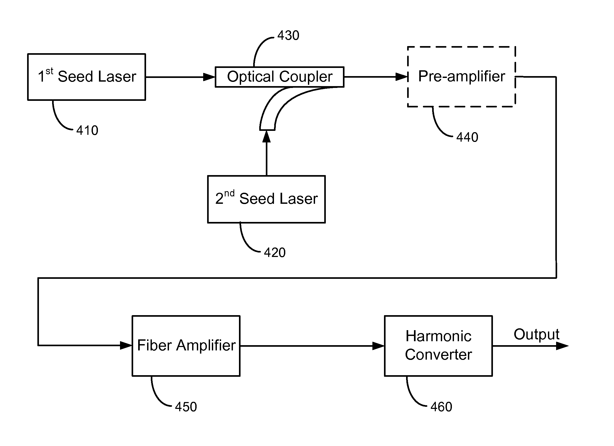
[0036]Embodiments of the present invention provide a harmonic fiber laser system with arbitrarily-controlled pulsetrains that is enabled by manipulating the optical characteristics of the master oscillator stage in conjunction with the NLO frequency conversion stage. The frequency conversion process serves as a very effective modulator: its efficiency relates to peak power, requires a well-defined polarization state, and necessitates a spectral bandwidth of less than a few nanometers. Note that the master oscillator may contain multiple seed lasers and multiple stages of amplification. Similarly, the power amplifier may contain multiple stages of amplification. The harmonic conversion stage may contain multiple stages of frequency conversion, including but not limited to second harmonic generation, third harmonic generation, fourth harmonic generation, sum frequency mixing, difference frequency mixing, or the like. By determinately and rapidly thwarting the sensitive conditions for ...


PUM


Abstract

A system for producing frequency converted light includes a first seed laser operable to provide a first laser signal and a second seed laser operable to provide a second laser signal. The system also includes an optical combiner optically coupled to the first seed laser and the second seed laser. The optical combiner is operative to combine the first laser signal and the second laser signal into a combined laser signal. The system further includes a power amplifier optically coupled to the optical combiner. An intensity of both the first laser signal and the second laser signal are increased by the power amplifier. The system additionally includes a harmonic converter optically coupled to the power amplifier.

Description

CROSS-REFERENCES TO RELATED APPLICATIONS[0001]This present application claims priority to U.S. Provisional Patent Application No. 61 / 021,584, filed on Jan. 16, 2008, the disclosure of which is hereby incorporated by reference in its entirety for all purposes.BACKGROUND OF THE INVENTION[0002]This invention relates generally to high performance laser systems. Merely by way of example, an embodiment of the present invention includes pulsed fiber laser sources that emit temporal pulses shorter than 10 ns with high peak power, narrow spectral linewidth, and arbitrary pulsetrains suitable for frequency conversion. However, the scope of the present invention is broader than this application and includes other laser systems.[0003]In some laser systems, a master-oscillator, power amplifier architecture is utilized in conjunction with a frequency conversion stage. The master oscillator emits a periodic train of temporally short, low power pulses. In some instances these pulses may have been s...

Claims


Application Information

Patent Timeline
IPC IPC(8): H01S3/10G02F1/35
CPCH01S3/0092H01S3/06754H01S3/2308H01S3/0912H01S3/1315H01S3/0809
Inventor MUNROE, MICHAEL J.
Owner LADARSYST INC
Learn More