Self-assembly micro blade

a micro blade and self-assembly technology, applied in the field of self-assembly micro blades, can solve the problems of volume error, poor accuracy, difficulty in manufacturing and cost rise, etc., and achieve the effect of increasing air flow rate and control, and improving air flow length

Inactive Publication Date: 2009-07-23
SUNONWEALTH ELECTRIC MACHINE IND
View PDF4 Cites 8 Cited by
  • Summary
  • Abstract
  • Description
  • Claims
  • Application Information

AI Technical Summary

Benefits of technology

[0022]The present invention pertains to a self-assembly micro blade applied to a micro fan. The micro fan combines at least one self-assembly micro blade and a motor using an actuator as the main body of the micro fan. The self-assembly micro blade includes at least a movable part of a microstructure, and at least an elastic joint provided between the movable part and an outer ring of the micro motor, composed of a polyimide film and generating surface tension by heating the elastic joint to result in thermal contraction through a reflow process so as to lift up the movable part of the microstructure in completion of the self-assembly micro blade.
[0023]A secondary object of the present invention is to provide a self-assembly micro blade providing a curved movable part so as to address increasing air flow rate and control and improved air flow length.

Problems solved by technology

Whereas, the aforementioned first type and second type of self-assembly techniques are only applicable to the microstructure in a static occasion or at a stationary position, making them not only inappropriate for manufacturing a component with displacing motion but also inappropriate for manufacturing a micro fan with rotary motion.
However, different material has its respective advantageous and disadvantageous characteristics.
Such additional step will result in difficulty while manufacturing and cost rise.
poor accuracy: While calculating elevation angle or displacement value of a microstructure, the ball size shall be accurately grasped.
However, lead tin alloy ball has a volume error up to 25%, making elevation angle or displacement value hard to be accurately controlled.
planar lifted microstructure: The microstructure lifted by elastic joints is limited to take a planar shape and fails to be curved.
miniaturization infeasibility: Current size of lead tin alloy ball is unable to be smaller than 100 μm, making the smallest size of elastic joint become relatively restrictive.
However, the cost of super critical CO2 dry release equipment used by the method is expensive.
Thus, the cost is relatively higher.
As a result, the originally manufactured elastic joint will be destructed.

Method used


Image

  • Self-assembly micro blade
  • Self-assembly micro blade
  • Self-assembly micro blade

Examples


Embodiment Construction

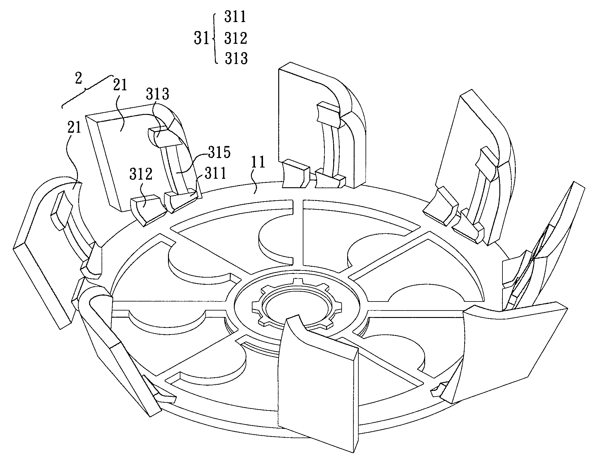
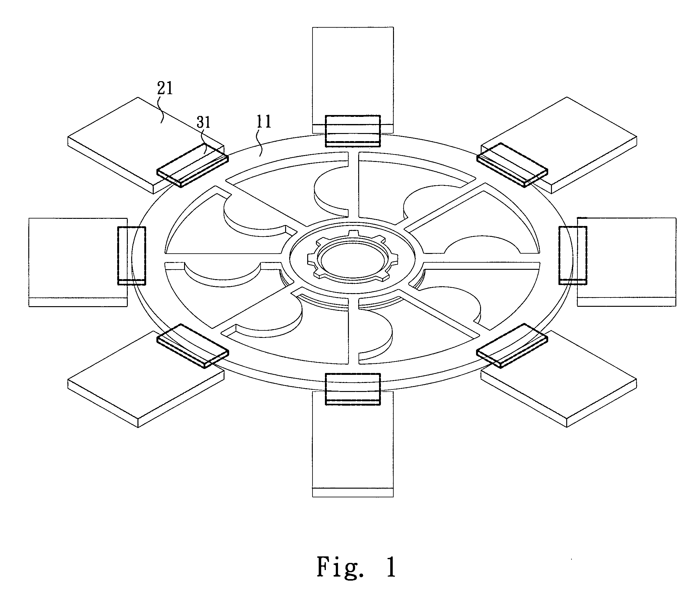
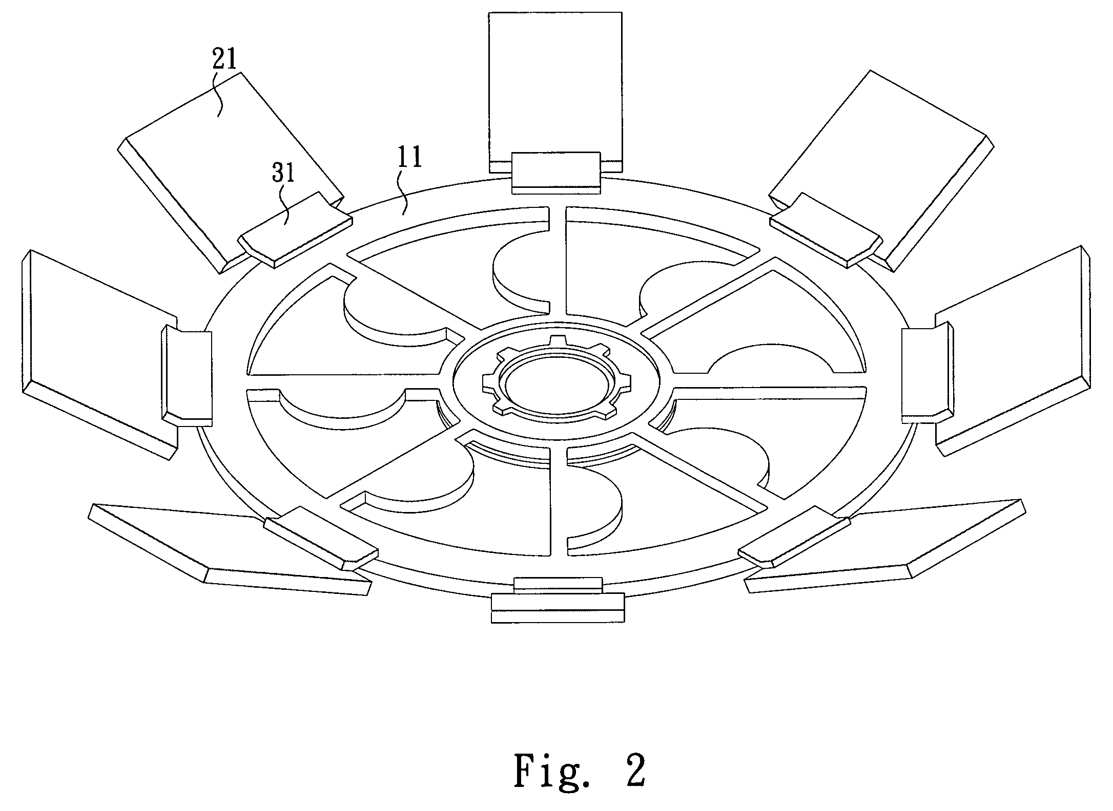
[0032]Please refer to FIG. 1 and FIG. 2. The present invention provides a first type of self-assembly micro blade to achieve a micro blade structure having movable parts. The self-assembly micro blade includes at least a movable part 21 of a microstructure, and at least an elastic joint 31 provided between the movable part 21 and an outer ring 11 of a micro motor. The elastic joint that is a photosensing ployimide film is heated to contract and generate surface tension after performing a reflow process in a high-temperature oven, so as to lift up the movable part of the microstructure and make the microstructure have a movable part for elevation while performing self assembly.

[0033]Please refer to FIG. 3. The present invention includes manufacturing processes of:

[0034](1) using plasma enhanced chemical vapor deposition method to deposit a phosphosilicate glass (PSG) on a silicon substrate 60 to serve as a low-stress sacrifice layer 70, and further using low pressure chemical vapor d...


PUM

PropertyMeasurementUnit
microstructureaaaaaaaaaa
surface tensionaaaaaaaaaa
stressaaaaaaaaaa

Abstract

The present invention relates to a self-assembly micro blade applied to a micro fan. The micro fan combines at least a self-assembly micro blade and a motor using an actuator as the main body of the micro fan. The self-assembly micro blade includes at least a movable part of a microstructure, at least an elastic joint provided between an outer ring of the micro fan and the movable part. The elastic joint is composed of a polyimide film, which is heated to contract and generate surface tension by using a reflow process so as to lift up the movable part of the microstructure; moreover, the movable part is bent in a curved form through the elastic link exhibits a multi-layer shape by serially connecting at least two movable parts so as to complete the self assembly of the micro blade, thereby increasing air flow rate and improving air flow length.

Description

FIELD OF THE INVENTION[0001]The present invention relates to a self-assembly micro blade for micro fan, which is characterized by providing additional flow rate and control and improvement of flow length so as to solve the drawbacks of conventional skill.BACKGROUND OF THE INVENTION[0002]Research and application of miniaturization technology is one of two major trends of modern science. In particular, self-assembly technique is a mainstream approach for assembling microstructure in microworld in recent years.[0003]As far as a micro fan manufactured by micro electromechanical systems (MEMS) technology is concerned, a scratch drive actuator (SDA) and a micro blade structure of the micro fan could only be built by virtue of self-assembly technique and multi-user MEMS processes (MUMPs).[0004]The so-called self-assembly technique means that a microstructure mechanism self-positions after completing the final release process. The current self-assembly technique has the following three type...

Claims


Application Information

Patent Timeline
Patent Type & Authority Applications(United States)
IPC IPC(8): B63H1/20
CPCF04D25/0613F04D29/30F04D29/281F04D29/023F05D2300/437F05D2300/434F05D2230/31
Inventor HORNG, ALEXHUANG, I-YUHUANG, CHUNG-JEN
Owner SUNONWEALTH ELECTRIC MACHINE IND
Why Eureka
Try Eureka