Method and system for multiphase current sensing

a multi-phase current and sensing technology, applied in the direction of motor/generator/converter stopper, dynamo-electric converter control, instruments, etc., can solve the problems of large power consumption, large impact on the overall cost of the inverter, and inability to accurately measure the current of the open-loop sensor, etc., to achieve less power and less expensive

Active Publication Date: 2009-07-30
GE HYBRID TECH
View PDF15 Cites 35 Cited by
  • Summary
  • Abstract
  • Description
  • Claims
  • Application Information

AI Technical Summary

Benefits of technology

[0017]It is a further object of this invention to provide such an improved system and method for multiphase circuit sensing which is robust, not sensitive to low frequency transients and does not employ high frequency signals with undesirable EMI emissions.
[0018]The invention results from the realization that a truly improved system and method for multiphase circuit sensing particularly suited for inverters, especially those used in moto

Problems solved by technology

Due to gain tolerances of the Hall sensor, tolerances on core material properties, and variations in the mechanical positioning of the sensor in the airgap, open-loop sensors are not very accurate (typically within 5-10% of rated output).
While closed-loop sensors offer advantages in terms of accuracy, they also have some significant drawbacks.
First and most importantly, their power-consumption is proportional to the measured current and can be quite large (several watts).
This difference is important, because power-supply requirements have a significant impact on the overall cost of the inverter.
Closed-loop sensors also tend to be larger and more expensive than open-loop sensors.
Those drawbacks are particularly penalizing for larger inverters, with output current exceeding 200-300 amps.
Since traction inverters are very cost sensitive, using closed-loop sensors in such applications is often not a viable option, and open-loop sensors are used instead.
However, if the gain-error of the sensors is not compensated for, the performance of the drive will suffer.
Besides torque linearity problems, gain-errors can also cause torque ripple and drive-train oscillations.
However, this operation is expensive and carries the overhead of handling individual calibration constants.
Furthermore, this approach can not address gain variations over time

Method used


Image

  • Method and system for multiphase current sensing
  • Method and system for multiphase current sensing
  • Method and system for multiphase current sensing

Examples


Embodiment Construction

[0043]Aside from the preferred embodiment or embodiments disclosed below, this invention is capable of other embodiments and of being practiced or being carried out in various ways. Thus, it is to be understood that the invention is not limited in its application to the details of construction and the arrangements of components set forth in the following description or illustrated in the drawings. If only one embodiment is described herein, the claims hereof are not to be limited to that embodiment. Moreover, the claims hereof are not to be read restrictively unless there is clear and convincing evidence manifesting a certain exclusion, restriction, or disclaimer.

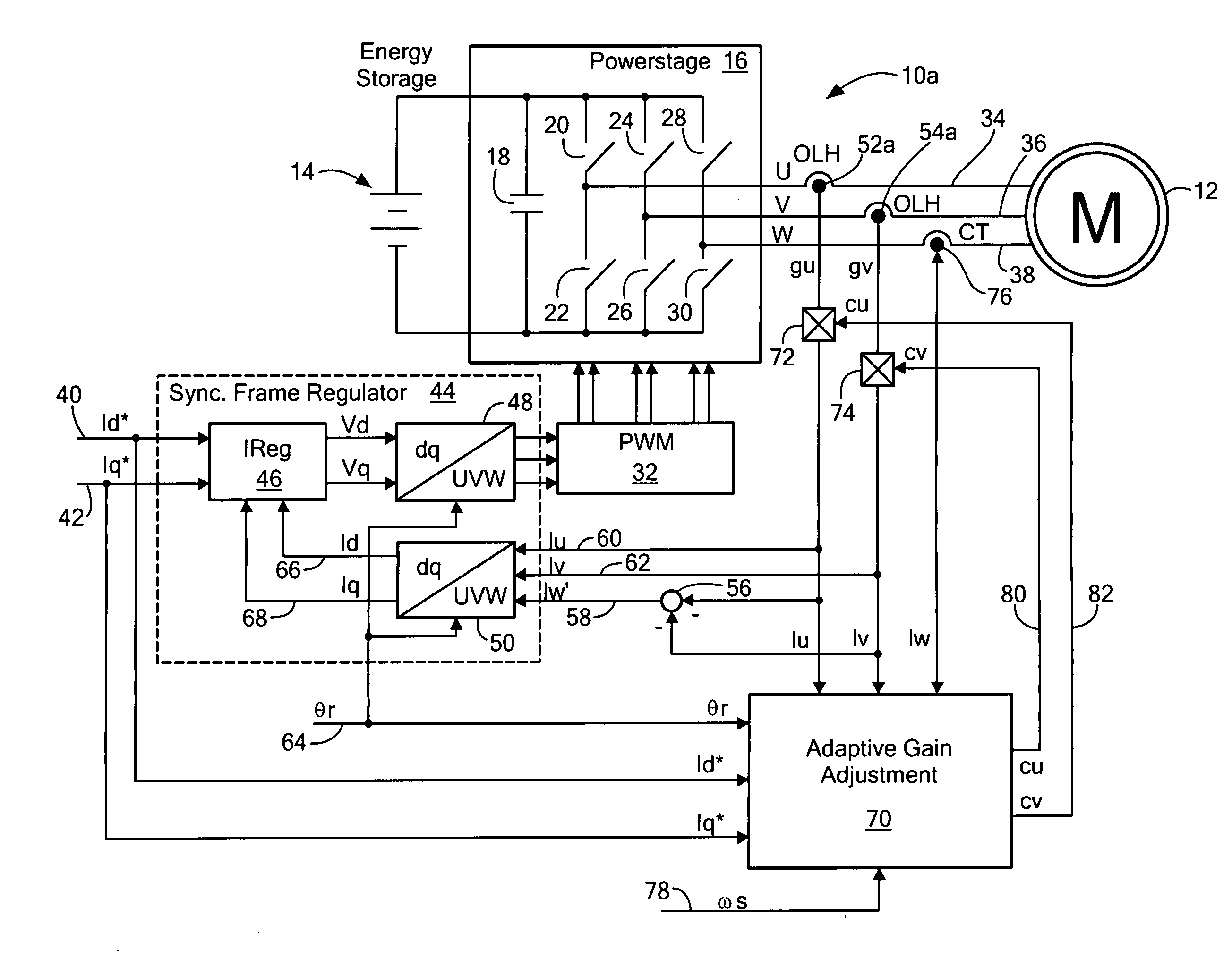
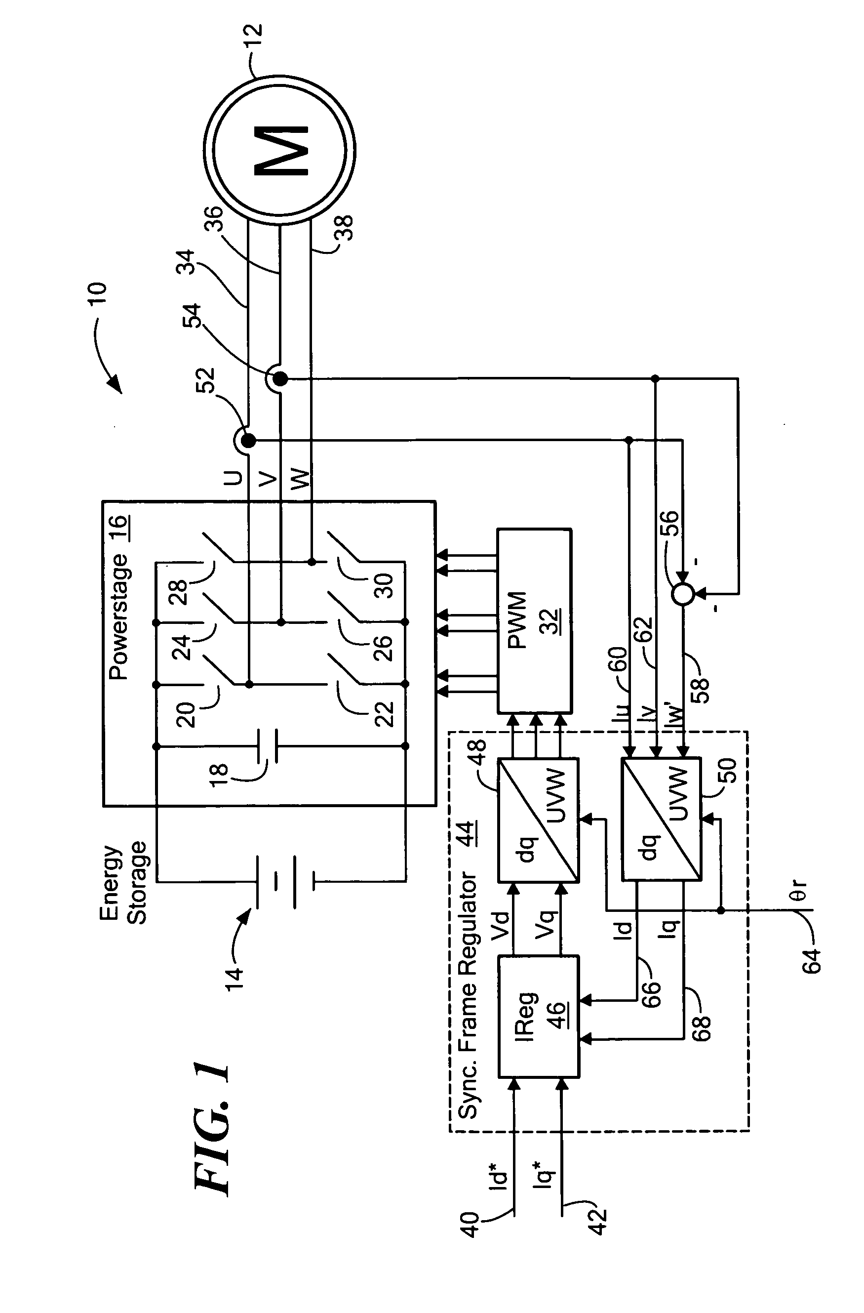
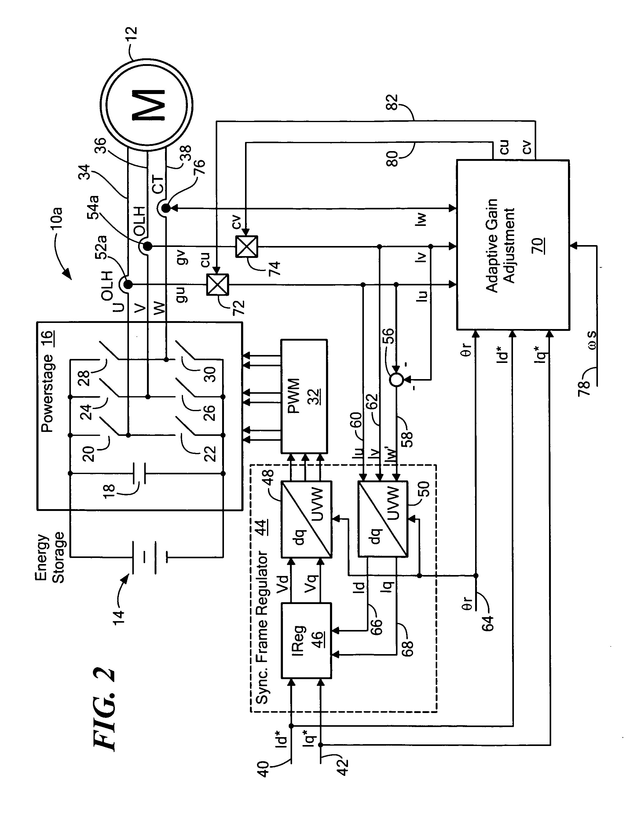
[0044]There is shown in FIG. 1 a motor control 10 for a three phase motor 12. Motor control 10 uses an energy storage device such as battery 14, to power a switching circuit 16 through a smoothing capacitor 18. Switching circuit 16 may include six switches 20, 22, 24, 26, 28 and 30 which may for example be insulated-gate bi...


PUM


Abstract

A multiphase current sensing method wherein the sum of the phase currents is zero including: sensing a.c. and/or d.c. currents in first and second phases; sensing a.c. current in a predetermined a.c. frequency range in a third phase; and combining the current sensed in the first and third phases and the second and third phases and determining a gain correction factor to be applied to the currents sensed in the first and second phases.

Description

FIELD OF THE INVENTION[0001]This invention relates to a method and system for multiphase current sensing and more particularly to a method and system adaptable for e.g. inverters for motor drives, photovoltaic inverters and uninterruptible power supplies.BACKGROUND OF THE INVENTION[0002]Hybrid vehicles require accurate control of the electric motor in order to achieve maximal fuel savings while ensuring good driveability and safety. The most prevalent control method for advanced traction motors is “field oriented control” (FOC). In FOC, the three-phase current wave-forms and voltage wave-forms (fixed frame) are transformed into a two-axis dq-frame which is rotating at the frequency o)s of the electrical waveforms (synchronous frame). By this coordinate transformation, a.c. waveforms result in d.c. vectors (also called space vectors). The advantage of this approach is that it is much easier to control d.c. quantities than a.c. quantities. The implementation of a digital current regul...

Claims


Application Information

Patent Timeline
IPC IPC(8): H02P6/08G01R29/16
CPCH02P21/0035G01R29/16H02P21/22
Inventor ARNET, BEAT J.
Owner GE HYBRID TECH
Why Eureka
Try Eureka