Supercapacitor

a supercapacitor and capacitor technology, applied in the direction of multiple hybrid/edl capacitors, reduction-oxidation hybrid capacitors, electrolytic capacitors, etc., can solve the problems of low power density, poor cycle life and safety, and the drawback of fuel automobiles

Inactive Publication Date: 2009-07-30
XIAMEN UNIV
View PDF6 Cites 7 Cited by
  • Summary
  • Abstract
  • Description
  • Claims
  • Application Information

AI Technical Summary

Benefits of technology

[0030]The supercapacitor according to the present invention accomplishes energy transformation by the electrode reaction of electrochemically active materials in the liquid phase, so it has higher energy density than existing various types of supercapacitors, and is an innovative pseudo-capacity-type supercapacitor. Because it is based upon a thin liquid layer of electrochemical active material to obtain pseudo-capacity, the supercapacitor of the present invention has a higher power density, longer cycle life, lower cost, and is safer relative to a conventional storage battery. The principle for the present invention is to take advantage of the electrochemical oxidization / reduction reaction of thin liquid layer of electrochemical active material on the electrode surface. In detail, the energy is stored in the chemicals with electrochemical activity in the thin liquid layer on electrode surface. During the charging course the electric energy is converted into chemical energy of active materials in the liquid phase. In contrast, during the discharging course the chemical energy in the aqueous phase is converted back into electric energy. The entire process does not involve solid phase reaction nor does it involve solid phase ion transport and embedment so the cycle life is long. The energy density correlates with the total amount of active materials in the liquid phase (if the concentration of active material is 2 mol / L, then the whole capacity density of supercapacitor will be up to 18 Ah / L or 15 Ah / kg). As such, the energy density does not have a direct relation to the surface area of solid electrode as in conventional prior art supercapacitors. The ion diffusion coefficient in the liquid phase is increased to more than 3 orders of magnitude than that in solid phase, therefore, the supercapacitor of the present invention has a higher power density, and the energy density is also higher than the existing supercapacitors. This allows the supercapacitors of the present invention to be suitable for use as a supplementary energy source for electrically-propelled mobiles to provide starting power and recycle braking energy. Urban mobiles (especially buses) need to start and brake during working frequently, so there will be remarkable economic effects to use the present invention.
[0031]Accordingly, the present invention provides an innovative energy storage device. Since the liquid inside the micropores of the porous electrode is non-flowing, the mass transfer mainly depends on diffusion and electromigration. The micropore size is very small and at any random point, the liquid in the micropore is very close to the porous electrode surface so the time from mass transfer to porous electrode surface is very short. When charging and discharging, the electrochemically active materials can rapidly mass transfer to the electrode surface to conduct the electrochemical reaction. Accordingly, they can be fully utilized to generate pseudo-capacity on a seconds time level with very high power output capability and furthermore no chemical and physical changes occur on the electrode solid phase before or after charging and discharging. In sum, the present invention has the following outstanding advantages (see Table 1).
[0032]1. The power density is very high (charge and discharge within 10 seconds or at a higher rate).
[0033]2. The electrochemical pseudo-capacity depends on the electrochemical active material content in thin liquid layer, and is much higher than that of electrochemical electric double layer supercapacitor, and also is higher than supercapacitor with solid phase process pseudo-capacity, and has higher single charging and discharging energy density.
[0034]3. Since no solid phase change occurs while charging and discharging, the cycle performance is excellent, and the life time is longer, the cycle life is two orders of magnitude higher than that of storage battery, therefore the charging and discharging “life-span energy density” (cycle number multiple single charging and discharging energy density) is higher than existing storage batteries and supercapacitors.
[0035]4. The electrochemical active materials can be selected broadly, and can use resource rich and environment friendly electrochemical active materials (for example vanadium, ferric, etc.).
[0036]5. The structure of battery is simple, the manufacturing cost is cheaper, and the materials can be early recycled.
[0037]Based on the above described advantages, the present invention can be used not only as ideal complementary power source for hybrid electric vehicle to recycle arresting energy and provide accelerating energy for startup, but also as the main energy source for pure electric vehicles need to be charged quickly at express public transit stations (loading and unloading time), furthermore, it can be used as high power source for military or civil uses.
TABLE 1Comparison of power sources of vehicles(pure electric and hybrid electric)StorageExistingPresentNo.ParameterbatterysupercapacitorinventionASpecific power*******BSpecific energy******CNormal rapidHourlyExtremelyTypicalcharging andshort10 sdischargingDCycling life*******ELife - span*******specific energy1FSimplicity for******manufactureGLow cost***, ******HCost*******performanceJResource****, ******feasibilityKEnvironmental**, *********protectionLMaintenance -**, *********free1= The total specific energy representatives the total kilometer number for power source.

Problems solved by technology

The drawbacks of fuel automobile, however, (especially in urban areas) are becoming very serious with the depletion of petroleum resources gasoline and the worsening of the environmental pollution caused by burning fossil fuels.
However, the storage batteries have the disadvantages of a lower power density, bad cycle life and safety problems, and cannot meet the desired power requirements.
But compared with storage batteries, the energy density of the supercapacitor with the electric double layer capacity is low.
(1) Chemical surface absorption and desorption as well as underpotential deposition on the electrode;
(2) Oxidation and reduction reaction of oxides membrane such as RuO2, IrO2 and Cr3O4 on the electrode surface;
(3) Doping and undoping of the electrically conductive polymer; however, the various pseudo-capacity supercapacitors have drawbacks such as, for example, a poor life cycle, high price, and other issues that prevent them from meeting the requirements of practical use.

Method used


Image

  • Supercapacitor
  • Supercapacitor
  • Supercapacitor

Examples


example 1

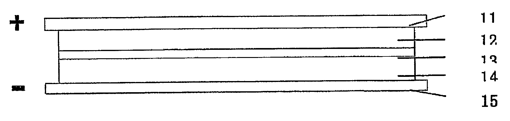
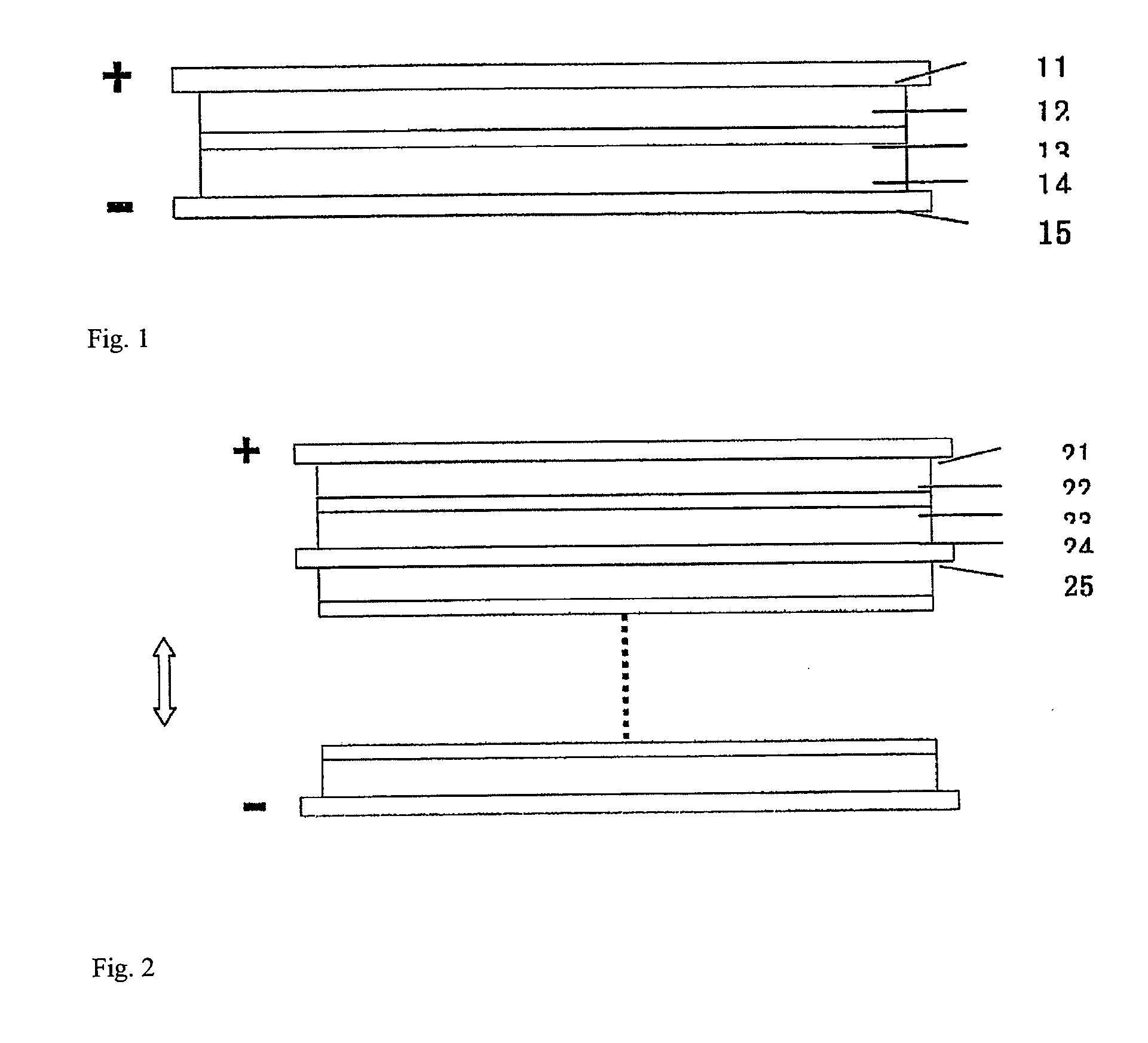
[0039]As shown in FIG. 1, the an embodiment of a supercapacitor according to the present invention comprises positive electrode collector 11, positive electrode chamber 12, separator membrane 13, negative electrode chamber 14, and negative electrode collector 15.

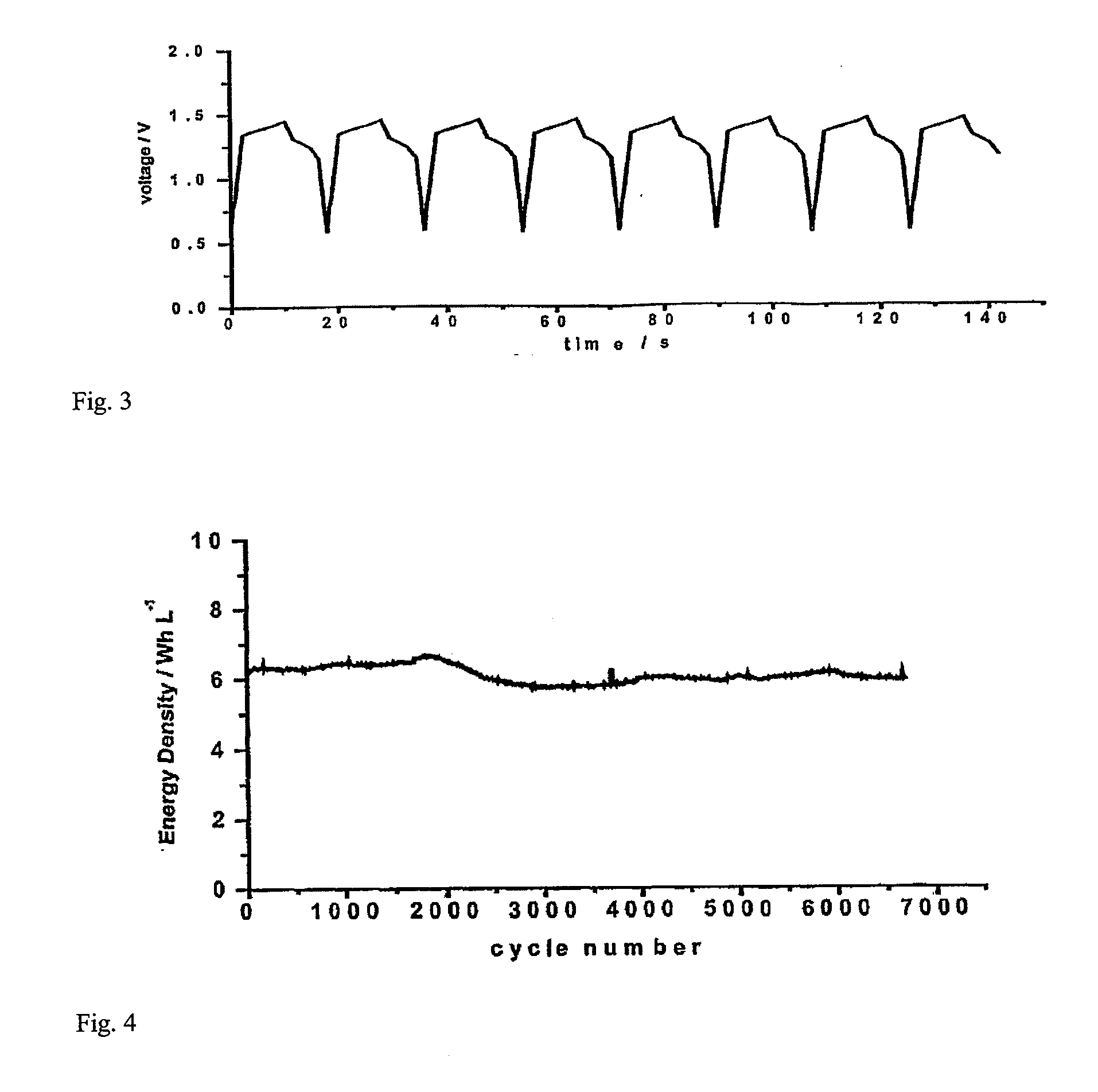
[0040]Graphite felt fabric was employed as both positive and negative chamber 12 and 14 of the supercapacitor. Positive and negative electrode chamber 12 and 14 also act as positive and negative electrodes, respectively. The thickness of the graphite felt fabric was 200 μm, the voidage was 90%. The thickness of positive electrode chamber and negative electrode chamber was from about 0.01 mm to 5.0 mm. 2M VOSO4 / (VO2)2SO4+1M H2SO4 was employed as the positive electrode electrolyte, and 2M VOSO4 / V2 (SO4)3+1M H2SO4 was employed as the negative electrode electrolyte. A cation exchange membrane was employed as separator membrane 13, and graphite was employed as positive and negative electrode collector 11 and 15. FIG. 3 shows the ...

example 2

[0042]As shown in FIG. 2, another embodiment of a supercapacitor according to the present invention comprises multiple capacitors in series. In this embodiment, a foam nickel plate was adopted as positive electrode chamber 22 of the supercapacitor, and the activated carbon was employed as negative electrode chamber 24. The thickness of the foam nickel was 2 mm, and the voidage was 90%. The thickness of the activated carbon was 5 mm, and the voidage is 50%. 2M FeSO4 / Fe2(SO4)3+1M H2SO4 was employed as the positive electrode electrolyte, while 2M Ti2(SO4)3 / TiOSO4+1M H2SO4 was employed as the negative electrode electrolyte. An anion exchange membrane was employed as separator membrane 23, and a nickel sheet was used as collector 21 and 25 of positive and negative electrodes, wherein negative electrode collector 25 was a positive and negative dipolar type collector.

example 3

[0043]In this example, the supercapacitor shown in FIG. 1 was employed.

[0044]Carbon fabric was employed as positive and negative electrode chamber 12 and 14 of the supercapacitor. Positive and negative electrode chamber 12 and 14 also act as the positive and negative electrodes. The thickness of the carbon cloth was 1 mm and the voidage was 60%. 2M VOSO4 / (VO2)2SO4+1M Ce(SO4)2 / Ce2(SO4)3+1M H2SO4 was employed as the positive electrode electrolyte and 2M (UO2)2SO4 / UO2SO4+1M H2SO4 was employed as the negative electrode electrolyte. An anion exchange membrane was employed as separator membrane 13, and a stainless steel sheet was employed as collector 11 and 15 of the positive and negative electrodes.


PUM

PropertyMeasurementUnit
sizeaaaaaaaaaa
thicknessaaaaaaaaaa
sizeaaaaaaaaaa

Abstract

The present invention provides a supercapacitor comprising: a) a positive electrode member comprising a solid material comprising pores and an electrically conductive current collector element bonded to said positive electrode member, wherein the pores comprise a non-flowing liquid comprising a first redox reagent; b) a negative electrode member comprising a solid material comprising pores and an electrically conductive current collector element bonded to said negative electrode member wherein the pores comprise a non-flowing liquid comprising a second redox reagent; and c) a separator member disposed between the positive electrode member and the negative electrode member, wherein the separator member comprising an ion exchange membrane, wherein the positive electrode member and the negative electrode member are bonded to opposite interface surfaces of the separator member.

Description

CROSS-REFERENCE TO RELATED APPLICATIONS[0001]This application is a National Stage entry under 35 U.S.C. § 371 of PCT / CN2007 / 001155 filed on Apr. 10, 2007, which claims priority to Chinese Application No. CN 200610087625.1, filed on Jun. 5, 2006. The entire contents of each of the above-applications are incorporated herein by reference.BACKGROUND OF THE INVENTION[0002]The present invention relates to a supercapacitor. In particular, it relates to a supercapacitor, the major energy storage method of which is based on the reaction of electrochemical active materials in the thin liquid layer near to the inner and outer surface of the porous electrodes.[0003]As the human society develops it has become more urgent to develop clean, highly efficient ways to utilize energy for the sustainable development of society. Fixed users can easily access the power supply network, whereas mobile users (such as automobiles) have to be dependent on energy storage devices. Such energy storage systems ma...

Claims


Application Information

Patent Timeline
Patent Type & Authority Applications(United States)
IPC IPC(8): H01G9/155
CPCH01G9/038H01G9/058H01G9/155Y02E60/13H01G11/12H01G11/26H01G11/58H01G11/02H01G11/22
Inventor TIAN, ZHAO-WUDONG, QUAN-FENGZHENG, MING-SENLIN, ZU-GENG
Owner XIAMEN UNIV
Why Eureka
Try Eureka