Slurry bed loop reactor and use thereof

Active Publication Date: 2009-08-06
CHINA PETROCHEMICAL CORP +1
View PDF6 Cites 11 Cited by
  • Summary
  • Abstract
  • Description
  • Claims
  • Application Information

AI Technical Summary

Benefits of technology

[0034]The slurry bed loop reactor provided in the present invention can fulfill the continuous, high efficient separation of solid catalyst particles, liquid products and reaction gases, and achieve the continuous discharge of the gas liquid solid three phases. Firstly, the circulation flow of the fluid inside the loop reactor achieves the continuous replacement of the concentrated slurry in the downcomers. Thus said reactor has a higher efficiency than the reactor using other separation means. Secondly, the relative high pressure inside the reactor forms a pressure drop between the slurry section and the filtrate section in the downcomers, which drives the slurry through the filter medium and achieves the solid liquid separation without any external driving force. In addition, the backpurging system is set up and can be flexibly operated, so that the filter medium is easily regenerated and the continuous operation of the whole reactor is ensured. The system

Problems solved by technology

In order to eliminate the diffusion effects, the catalyst in a size of scores of micrometers, or even in the form of finer particles is generally used in the slurry bed reactor, which is also accompanied by the difficult problem of the separation of the reaction product from the catalyst particles.
Such process, however, will readily lead to breakage of the catalyst particles, so as to bring problems to the continuous operation of the reactor for a long period of time.
However, the complete liquid solid separation achieved by a single settling technique to obtain the liquid product having an extremely low solid content requires a settling device having a very great volume to ensure sufficient settling time, which results in that most of the area and space of the equipment are occupied by the settling device and leads to relatively low production efficiency.
Meanwhile, solid powder having an extremely particle size will be produced during the reaction due to catalyst abrasion.
The effect of the settling technique for the catalyst particles in a size of several micrometers, or even in a smaller size, however, is not good.
Since the Fischer-Tropsh Synthesis reactor has a relatively great diameter, the magnetic field device is difficult to produce homogeneous magnetic f

Method used


Image

  • Slurry bed loop reactor and use thereof
  • Slurry bed loop reactor and use thereof
  • Slurry bed loop reactor and use thereof

Examples


example 1

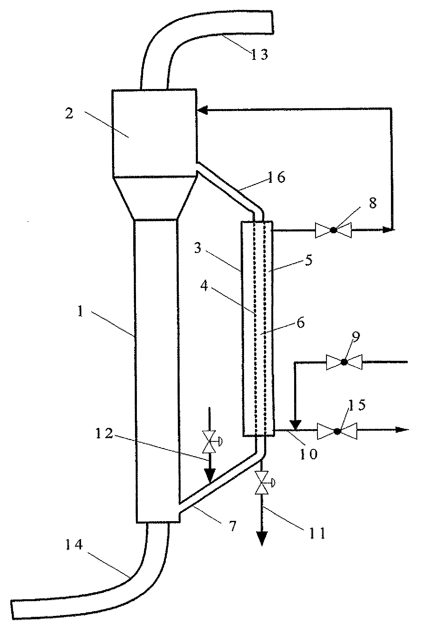
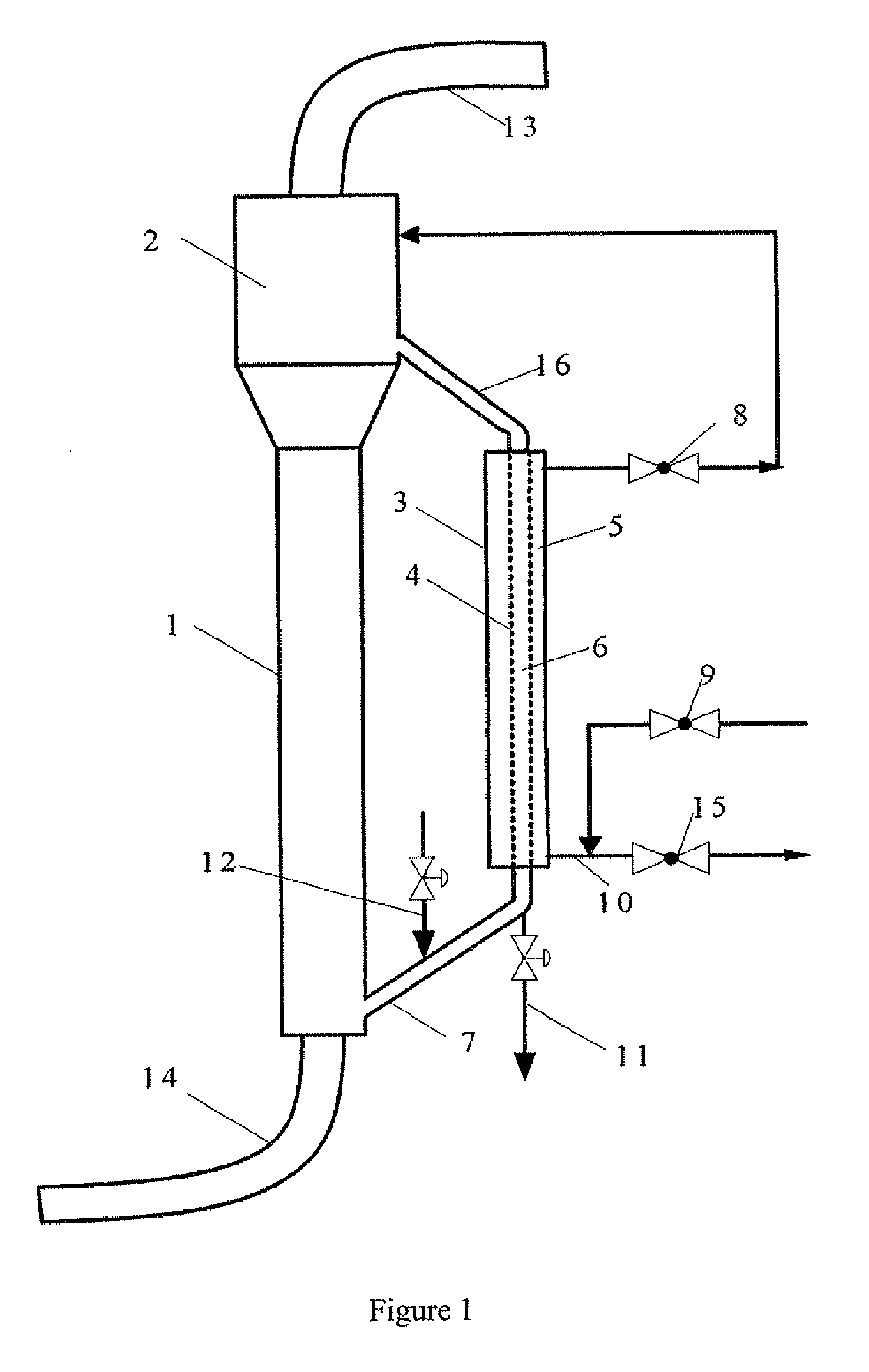
[0050]The reactor as shown in FIG. 1 is used. The riser settling section (2) and the reaction section (1) in the slurry bed loop reactor have a tube diameter ratio of 1.5:1. The filter tube used in the downcomers is the sintered metal porous filter tube having an outer diameter of 50 mm, a length of 1,000 mm and an average pore diameter of 1 μm. The particle size of the catalyst used therein ranges from 1 to 100 μm. During such process, the synthetic gas enters the bed layer in a bubbling form from the bottom of the riser, and forms the liquid hydrocarbons under the operating conditions. After the slurry rises to the settling section, the unreacted synthetic gas and the gas product are completely separated from the slurry, and discharged from the outlet. Coarse catalyst particles (about 80% of the total amount of the catalyst) in the slurry settle down in the settling section and return to the riser. The slurry enters the filter tube of the downcomer, and the liquid product enters t...

example 2

[0053]The slurry bed loop reactor as shown in FIG. 1 is used. The riser settling section and the reaction section in the reactor have a tube diameter ratio of 1.5:1. The filter tube used in the downcomers is the sintered metal porous filter tube having an outer diameter of 50 mm, a length of 1,000 mm and an average pore diameter of 1 μm. The particle size of the catalyst used therein ranges from 1 to 100 μm. The raw material is the synthetic gas. When the differential pressure between the inner and outer tubes of the downcomer is higher than 0.5 MPa, the back purging system goes into operation. The product supernatant is introduced to the outer tube with a pump, and into the inner tube through the wall of the filter tube. The filter cake is purged to the slurry and flows downwardly along with the slurry to the riser. This process lasts several seconds. When the differential pressure between the inner and outer tubes is lower than 0.1 MPa, the back purging system closes, and the slur...

example 3

[0055]The reactor as shown in FIG. 9 is used. Said turbulence section (20) is separated from the steady flow section (19) by said cylindrical baffle, and the bottom of said steady flow section (19) is connected to the reaction section via the hole(s) at the bottom of the baffle. The reaction section has a size of Ø70×3200 mm. The expanding section of the settling section has a tube diameter of 150 mm and a height of 1000 mm. The cylindrical baffle have a size of Ø70×700 mm, and 6 holes in a size of Ø12 at the bottom thereof. The outer tube of the downcomers has a size of Ø70×2000 mm, and the inner filter tube is made of metal microporous membrane and has a size of Ø30×1800 mm and an average pore diameter of 1.0 μm.

[0056]The catalyst comprises 20.3% by weight of Co2O3, 76.1% by weight of SiO2, and 3.6% by weight of MgO. It is prepared by impregnating SiO2 microspheric carriers with a solution containing Co(NO3)3 and Mg(NO3)2, then standing for 24 h, drying at 120° C., calcining at 40...


PUM

PropertyMeasurementUnit
Temperatureaaaaaaaaaa
Pressureaaaaaaaaaa
Pressureaaaaaaaaaa

Abstract

The present invention relates to a slurry bed loop reactor comprising a riser and at least one downcomer (3), wherein two ends of the riser are connected to two ends of the downcomer (3) via lines (16) and (7), respectively. The riser comprises a reaction section (1) and a settling section (2) with an increased tube diameter disposed on the reaction section (1). A gas outlet (13) exists at the top of the settling section (2). Each of the downcomers (3) is divided into a filtrate section (5) and a slurry section (6) by filter medium (4), wherein the filtrate section (5) is connected to a liquid outlet (10); two ends of the slurry section (6) are respectively connected to two ends of the riser, and the filtrate region (5) may further be connected to a back purging system. When used in a gas-liquid-solid three phases reaction system, the reactor can realize successive separation of gas, liquid and solid particles in slurry, and realize the back purging regeneration of filter tubes without influencing the reaction processes. In addition, said reactor has the advantages of high separation efficiency, simple structure, flexible and easy operation

Description

TECHNICAL FIELD[0001]The present invention relates to an apparatus and process for separating solid particles from liquid, more specifically to an apparatus for continuously separating liquid from solid particles in a slurry bed loop reactor and a process for utilizing the same.BACKGROUND OF THE INVENTION[0002]A slurry bed reactor is a common gas-liquid (slurry) contact reaction equipment and has an extremely high liquid storage capacity. As for a catalytic reaction process having very great heat of reaction, the slurry bed reactor can effectively remove heat of reaction, achieve isothermal operation of the reactor, and guarantee the normal operation of the reactor. Hence, said reactor is widely used in the current chemical engineering industry. The slurry bed loop reactor, however, is a high effective, multiphase reactor developed on the basis the slurry bed bubbling reactor. Besides all the advantages of the slurry bed bubbling reactor, the slurry bed loop reactor further enables ...

Claims


Application Information

Patent Timeline
IPC IPC(8): C07C27/06B01J8/20
CPCB01J8/006B01J2208/0084B01J8/228B01J8/226
Inventor ZHANG, ZHANZHUHU, LIFENGTANG, XIAOJINWANG, SHAOBINGHOU, SHUANDIMAO, JUNYIQU, HONGLIANG
Owner CHINA PETROCHEMICAL CORP
Why Eureka
Try Eureka