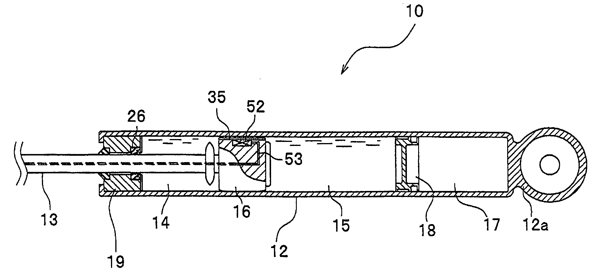
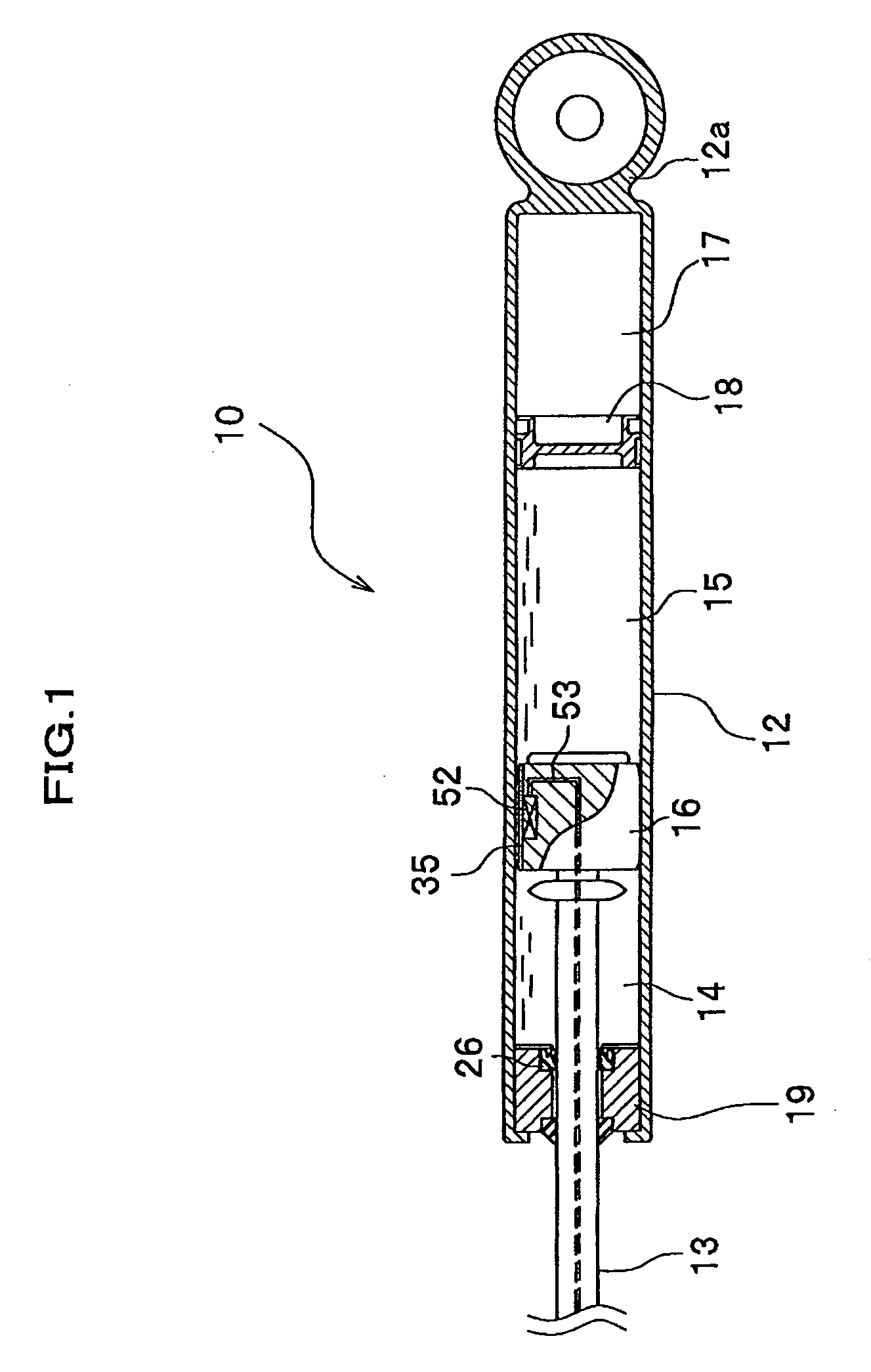
Variable damping-force damper and manufacturing method of the same

a damping force and damper technology, applied in the field of variable damping force dampers, can solve the problems of increasing production costs, reducing productivity and production costs, and hard to form cr plating films whose vickers hardness exceeds 1000 vhn by cr plating, etc., and achieves excellent durability, reduce sliding resistance, and reduce sliding resistance

Inactive Publication Date: 2009-08-13
HONDA MOTOR CO LTD
View PDF6 Cites 69 Cited by
  • Summary
  • Abstract
  • Description
  • Claims
  • Application Information

AI Technical Summary

Benefits of technology

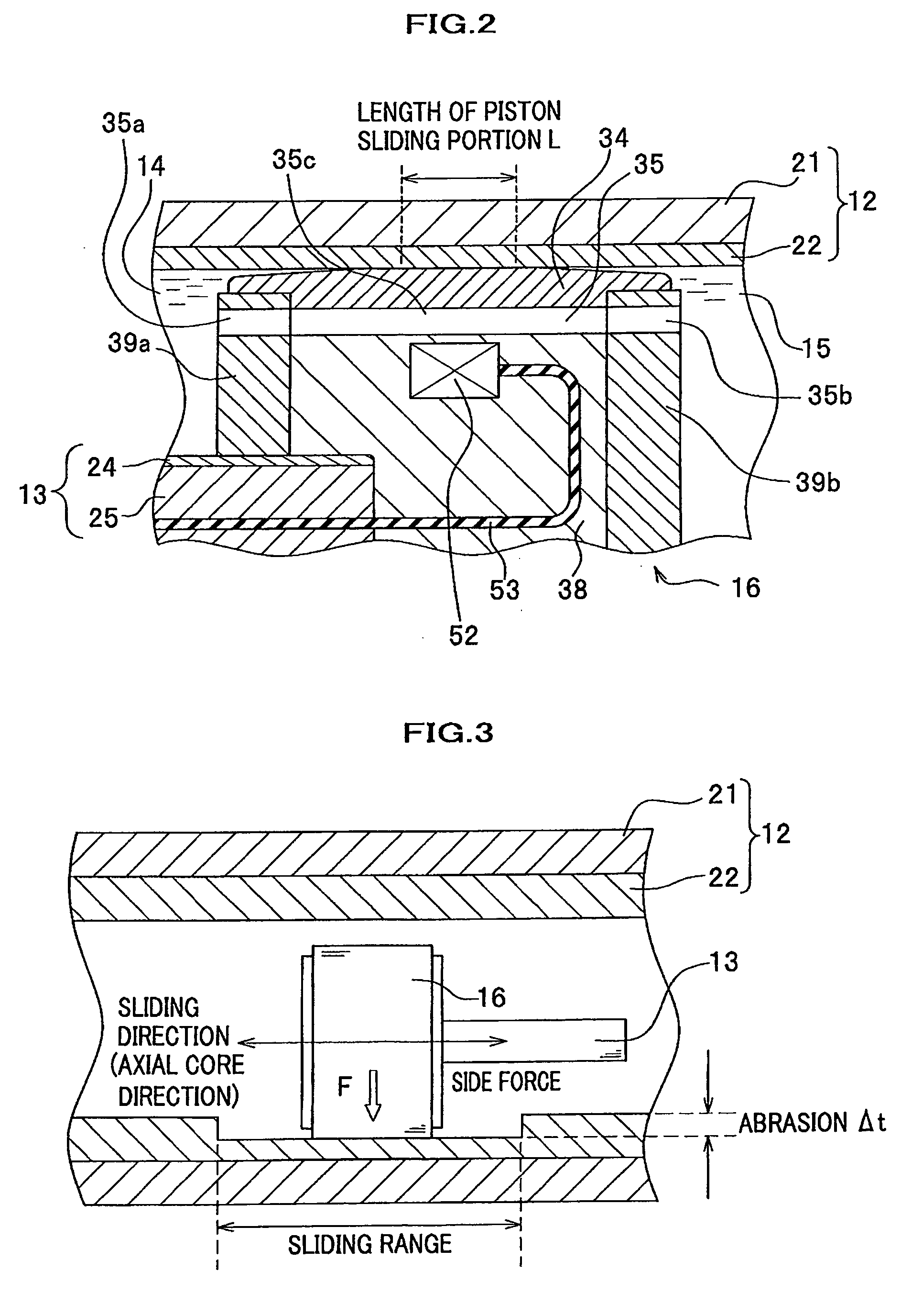
[0044]It becomes possible to reduce the sliding resistance between the piston rod and the rod guide because the second electroless nickel plating layer slides relative to the rod guide in an initial period of usage of the variable damping-force damper. When the second electroless nickel plating layer abrades with time, the sliding resistance decreases because the clearance between the piston rod and the rod guide is widened. At this time, the first electroless nickel plating layer that has the hardness harder than the second electroless nickel plating layer slides relative to the rod guide, so that the first plating layer can suppress the advance of abrasion of the first electroless nickel plating layer. Thus, it becomes possible to keep the excellent durability.
[0045]Preferably, the rod guide is provided with a sealing member to prevent the working fluid from leaking out of the cylinder tube in the variable damping-force damper of the invention. It is also preferable to provide the sealing member on the side closer to the piston rather than the electroless Ni plating film in the axial core direction of the cylinder tube. Thereby, the sealing member can reduce a number of the magnetic particles entering the sliding surface between the rod guide and the piston rod and can suppress the abrasion of the both sliding surfaces of the rod guide and the piston rod.
[0046]Preferably, the piston rod is provided with an electroless Ni plating film or a Cr plating film on the sliding surface thereof with a thickness of 10 μm or more and a surface roughness of 0.1 to 1.5 in terms of a Rz value. It becomes possible to reduce the magnetic particles entering the gap between the piston rod and the rod guide and to suppress the abrasion of the sliding surface by smoothing the surface of the piston rod.
[0047]As described above, according to the present invention, it is possible to obtain the excellent abrasion resistance and to reduce the abrasion by forming the highly hard Ni plating fil

Problems solved by technology

In contrary to that, it is hard to form a Cr plating film whose Vickers hardness exceeds 1000 VHN by Cr plating.
However, if the thickness of the Ni plating film 22 is increased more than what is required, it drops productivity and increases a production cost.
That is, there is a problem that the

Method used


Image

  • Variable damping-force damper and manufacturing method of the same
  • Variable damping-force damper and manufacturing method of the same
  • Variable damping-force damper and manufacturing method of the same

Examples


embodiments

[0152]Firstly, a result of a durability test of the Ni plating film formed on the inner peripheral surface of the cylinder tube will be explained by assuming a case when the variable damping-force damper is used as a suspension of a vehicle.

first embodiment

Variable-Damping Force Damper of First Embodiment

[0153]A Ni plating film was formed on an inner peripheral surface of a cylinder base material made of a steel pipe for general structure so that its average thickness becomes 40 μm with forming speed of 0.1 μm / min. by using an electroless Ni plating solution and was then heat-treated in 315 to 327° C. for two hours. Thus, the cylinder tube having the Ni plating film (Ni—P plating film) whose Vickers hardness is 900 VHN and whose surface roughness (average height of+point Rz) is 1.3 μm and inner diameter of about φ 46 mm (tolerance: less than 5 μm) was obtained. It is noted that the Vickers hardness and the surface roughness of the Ni plating film were measured respectively by means of a commercially available Vickers hardness tester and a surface roughness meter by using a Ni plating film formed by simultaneously treating a flat plate made of a steel plate for general structure, i.e. the same material with the cylinder base material. ...

second embodiment

Variable-Damping Force Damper of Second Embodiment

[0155]A Ni plating film was formed on an inner peripheral surface of a cylinder base material that is the same one with the cylinder base material used in the fabrication of the variable damping-force damper of the first embodiment so that its average thickness becomes 40 μm with forming speed of 0.1 μm / min. by using a plating solution in which BN powder is dispersed in the electroless Ni plating solution used in the first embodiment and was then heat-treated in 315 to 327° C. for two hours. Thus, the cylinder tube having the Ni plating film (Ni—P+BN plating film) whose Vickers hardness is 900 VHN and whose surface roughness (average height of+point Rz) is 1.3 μm and an inner diameter of about φ46 mm (tolerance: less than 5 μm) was obtained. The variable damping-force damper of the second embodiment was fabricated by using the cylinder tube and a piston equivalent to the piston used in the fabrication of the variable damping-force da...


PUM

PropertyMeasurementUnit
Thicknessaaaaaaaaaa
Thicknessaaaaaaaaaa
Thicknessaaaaaaaaaa

Abstract

A variable damping-force damper includes a cylinder tube filled with magnetic particles (MRF), a piston that is slidably disposed within the cylinder tube, a piston rod connected with the piston and is disposed so as to protrude out of one end of the cylinder tube and a rod guide that closes one end of the cylinder tube and slidably supports the piston rod. The cylinder tube has a Ni plating film whose Vickers hardness is 800 VHN or more on its inner peripheral surface and the piston slides relative to the Ni plating film. The rod guide has a structure having a predetermined base material portion and a fluorine resin contained Ni plating film that is treated by heat and is provided on the surface of the base material portion. The piston rod slides relative to the fluorine resin contained Ni plating film.

Description

CROSS REFERENCE TO RELATED APPLICATIONS[0001]The present application claims the benefit under 35 U.S.C. 119 of Japanese Patent Application 2008-30763 filed on Feb. 12, 2008, Japanese Patent Application 2008-89065 filed on Mar. 31, 2008 and Japanese Patent Application 2008-150528 filed on Jun. 9, 2008, the disclosures of which are incorporated in this application by reference.BACKGROUND OF THE INVENTION[0002]1. Field of the Invention[0003]The present invention relates to a variable damping-force damper and more specifically to a variable damping-force damper for use in damping vibrations of a vehicle or the like for example as well as to a manufacturing method of the same.[0004]2. Description of Related Art[0005]There is known a variable damping-force damper using a MRF (Magneto-Rheological Fluid) as a working fluid in which spherical particles having an average size of around several μm and ferromagnetism (referred to as “magnetic particle” hereinafter) are dispersed as a dispersed ...

Claims


Application Information

Patent Timeline
IPC IPC(8): F16F9/53B23P13/00
CPCY10T29/49615F16F9/535
Inventor KONDO, YOHEIAMANO, HIDETOSHIYAMASHITA, SHINJIKAJIWARA, HAJIMEOGASA, HIROSHIAZEKATSU, YOSHITOMO
Owner HONDA MOTOR CO LTD
Why Eureka
Try Eureka