High power impulse magnetron sputtering vapour deposition

a magnetron sputtering and high-power technology, applied in the direction of electrodes, diaphragms, ion implantation coatings, etc., can solve the problems of low target utilisation, low ion flux in the vicinity of the substrate, and limited maximum average target power density, so as to reduce plasma losses, reduce the time taken, and limit the effect of deposition ions

Inactive Publication Date: 2009-08-13
SHEFFIELD HALLAM UNIVERSITY
View PDF5 Cites 24 Cited by
  • Summary
  • Abstract
  • Description
  • Claims
  • Application Information

AI Technical Summary

Benefits of technology

[0026]Preferably, the apparatus further comprises means to change the magnetic field strength created by the array of magnets at the target wherein the apparatus is capable of creating a plurality of different discharge current densities at the target for a given voltage. The array of magnets may be moveably mounted relative to the target such that distance between the target and the array of magnets may be adjusted. This particular embodiment is advantageous and serves to decrease the time taken for the entire coating process involving initial pretreatment and subsequent metal deposition. The distance between the magnets or electromagnetic coils may be adjusted using known electronic or mechanical devices which may be operated externally to the internal sputtering vacuum chamber.
[0027]Preferably, the apparatus further comprises a magnetron or a plurality of magnetrons and an electrode biased to a ground or positive potential that serves as an anode as described in U.S. Pat. No. 6,352,627. In particular, the apparatus may further comprise an anodic electrode within the deposition chamber having a positively biased voltage relative to the chamber walls which are preferably earthed. This particular embodiment is advantageous and serves to direct the plasma flow away from the chamber walls and on to the anode thereby decreasing substantially plasma losses.
[0028]Preferably, the apparatus further comprises a pair of facing magnetrons with opposing magnetic fields or an even number of magnetrons with alternating magnetic field polarity. This particular embodiment is advantageous and serves to create a closed loop magnetic field trap enclosing the entire chamber thus limiting the losses of deposition ions to the chamber walls and improving the deposition rate on the substrates. The field strength may be adjusted by additional magnets or electromagnets using known electronic or mechanical devices to regulate the trapping efficiency.
[0029]Optionally, the present apparatus may comprise a pair of magnetrons operated out of phase according to a bipolar pulsed technique (dual magnetron sputtering) as disclosed in Surface and Coatings Technology 98 (1998) 828-833. Accordingly, in alternate pulses the first magnetron serves as a cathode and the second as an anode of the discharge and in the next pulse the first magnetron serves as an anode and the second as a cathode. This could be advantageous for example in the deposition of oxide films to limit the build-up of charge that can lead to arcing.
[0030]Where the apparatus further comprises means to change the magnetic field strength created by the array of magnets at the target the apparatus may further comprise an additional duct parallel to the target-substrate path with magnetic field normal to the target. The magnetic field may be generated by permanent magnets or electromagnets. This particular embodiment is advantageous and serves to further improve deposition rates by promoting the transport of electrons and highly ionised plasma originating from the target material from the target to the substrate. In this embodiment, the deposition rate can be increased for single or a plurality of cathodes without the need for an even number of magnetrons or cathodes in a closed field magnetic system. The field strength in the duct may be adjusted using known electronic or mechanical devices to regulate the transport efficiency.

Problems solved by technology

However limitations of this process included low target utilisation and low ion flux in the vicinity of the substrate.
The maximum average target power density is however limited by a number or factors including target overheating, plasma instability and arcing.
The magnetic field is configured such that electrons are trapped in the vicinity of the target and follow a helical motion, which increases their path length in the given volume and increases the probability of ionising the working gas and sputtered metal neutrals.
However, whilst it is possible to generate coatings of superior quality using HIPIMS rather than convention dcMS, in general deposition rates are significantly lower.
Once ionised, a large fraction of these ions are accelerated back towards the sputtering target by the electric field of the cathode and become unavailable for deposition, instead contributing to the sputtering current.
Whilst a number of workers have investigated deposition rates, the deposition rate difference between dcMS and HIPIMS, with considerable ionisation degree, remains unsatisfactorily large.

Method used


Image

  • High power impulse magnetron sputtering vapour deposition
  • High power impulse magnetron sputtering vapour deposition
  • High power impulse magnetron sputtering vapour deposition

Examples


Embodiment Construction

[0036]There will now be described by way of example a specific mode contemplated by the inventors. In the following description numerous specific details are set forth in order to provide a thorough understanding. It will be apparent however, to one skilled in the art, that the present invention may be practiced without limitation to these specific details. In other instances, well known methods and structures have not been described in detail so as not to unnecessarily obscure the description.

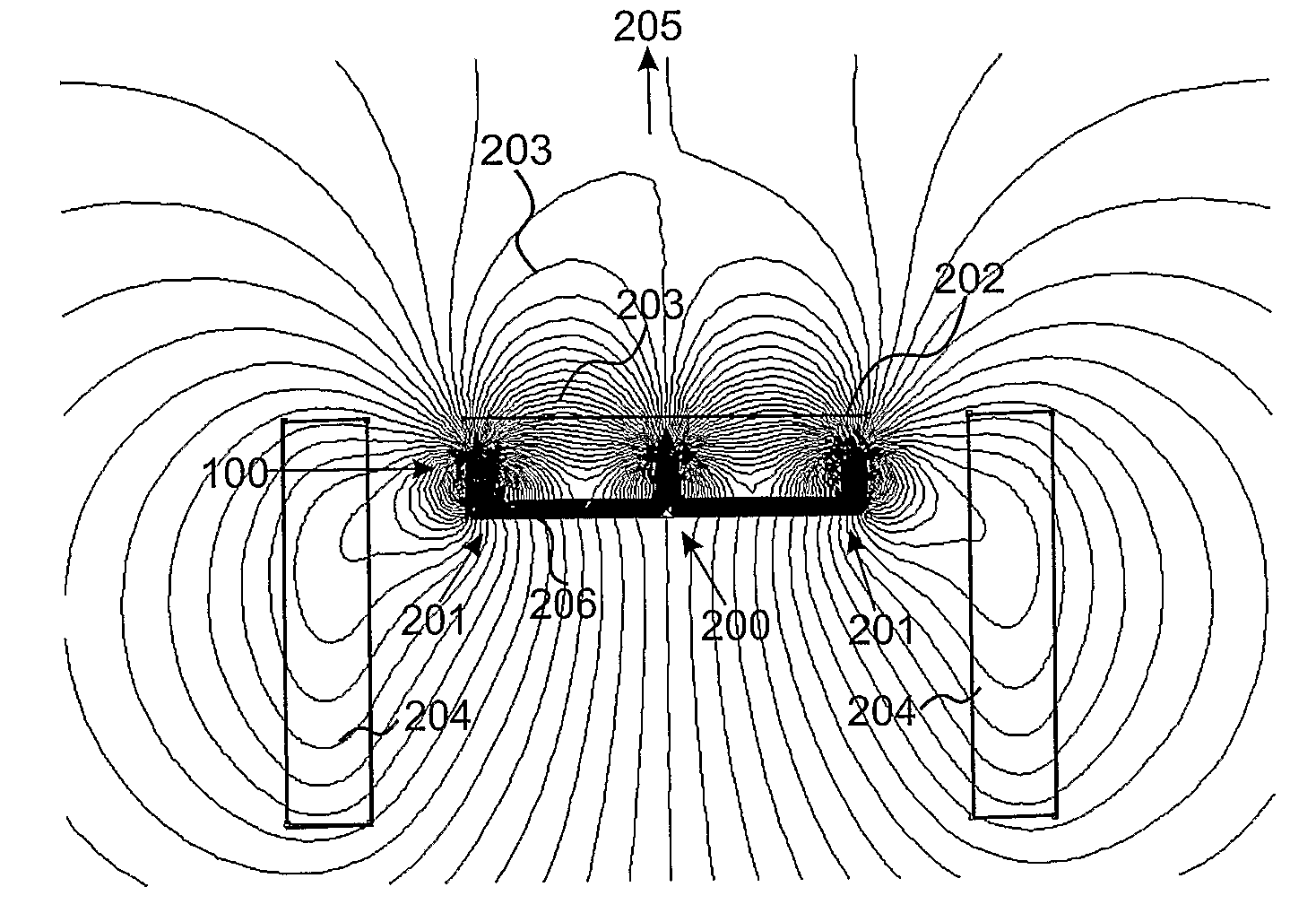
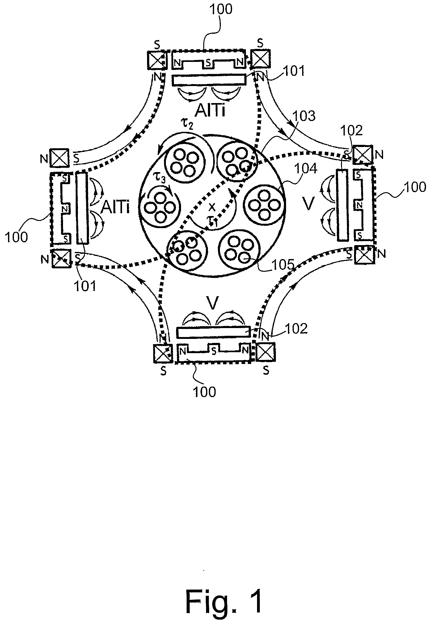
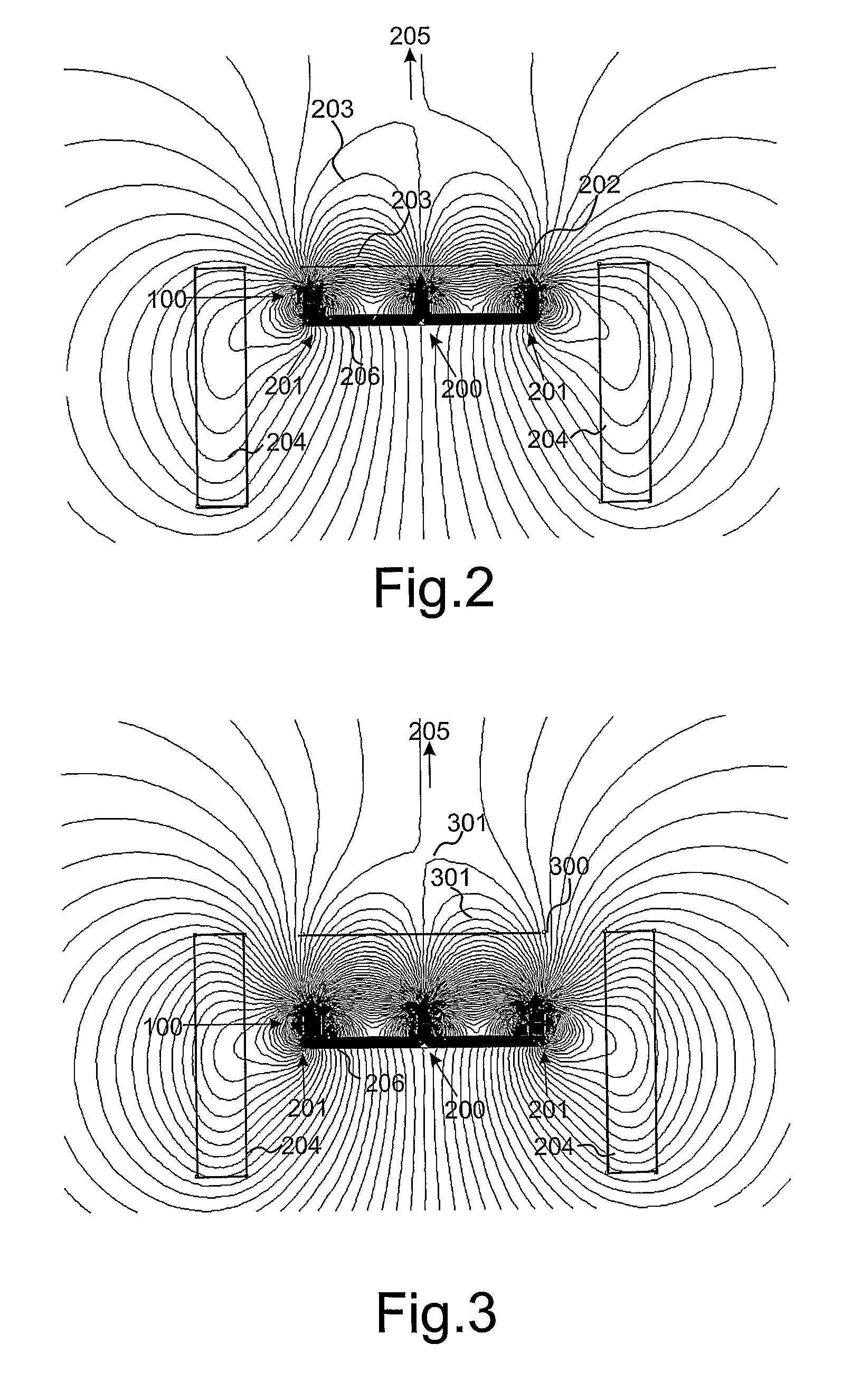
[0037]An investigation was undertaken to determine the influence of magnetic field strength in the proximity of the target on the deposition rate of metal ions deposited via a HIPIMS process.

[0038]Although magnetron systems are designed to influence only the electrons, metal ions are also confined indirectly via an ambipolar interaction with electrons. This interaction forces both species to exist in equilibrium in order to sustain quasineutrality which is a fundamental property of the plasma....


PUM

PropertyMeasurementUnit
magnetic fieldaaaaaaaaaa
discharge current densityaaaaaaaaaa

Abstract

Method and apparatus for physical vapour deposition (PVD) and in particular high power impulse magnetron sputtering (HIPIMS) deposition is described. The present apparatus and process provide for the creation of a weaker magnetic field in the region of the cathode which reduces the confinement of a significant part of the plasma near the target surface. By weakening the magnetic field in the region of the target, the deposition rate of materials at a substrate has been found to increase by a factor of 9 relative to that of conventional HIPIMS processes employing typical magnetic field strengths.

Description

FIELD OF THE INVENTION[0001]The present invention relates to high power impulse magnetron sputtering (HIPIMS) physical vapour deposition (PVD) processes and apparatus and in particular a process and apparatus that provides an enhanced metal or compound deposition rate.BACKGROUND TO THE INVENTION[0002]Physical Vapour Deposition (PVD) processes have been widely used for depositing thin films on substrates. Magnetron sputtering refers to the technique in which an external magnetic field is applied directly to a sputtering source to confine plasma electrons and increase the sputtering rate. One early magnetron sputtering technique employed was direct current magnetron sputtering (dcMS). However limitations of this process included low target utilisation and low ion flux in the vicinity of the substrate. This technique has been found to produce films having a porous microstructure due to low metal ionisation of the deposition flux from the target (cathode). Another well established techn...

Claims


Application Information

Patent Timeline
Patent Type & Authority Applications(United States)
IPC IPC(8): C23C14/35H01J37/34
CPCC23C14/352H01J37/3467H01J37/3461H01J37/3408H01J37/3455H01J37/3458C23C14/35
Inventor EHIASARIAN, ARUTIUN P.
Owner SHEFFIELD HALLAM UNIVERSITY
Why Eureka
Try Eureka