

Optical film, method for producing the same, polarizing plate and image display device
a technology of optical film and polarizing plate, which is applied in the direction of polarizing elements, instruments, transportation and packaging, etc., can solve the problems of affecting the appearance of the film, reducing the productivity, and increasing the coating cost, so as to achieve the effect of high physical strength and regulation of the coating composition
- Summary
- Abstract
- Description
- Claims
- Application Information
AI Technical Summary
Benefits of technology
Problems solved by technology
Method used
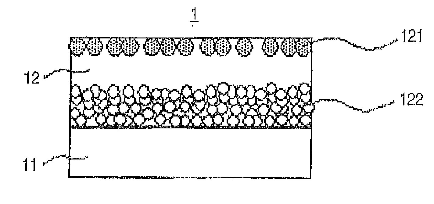
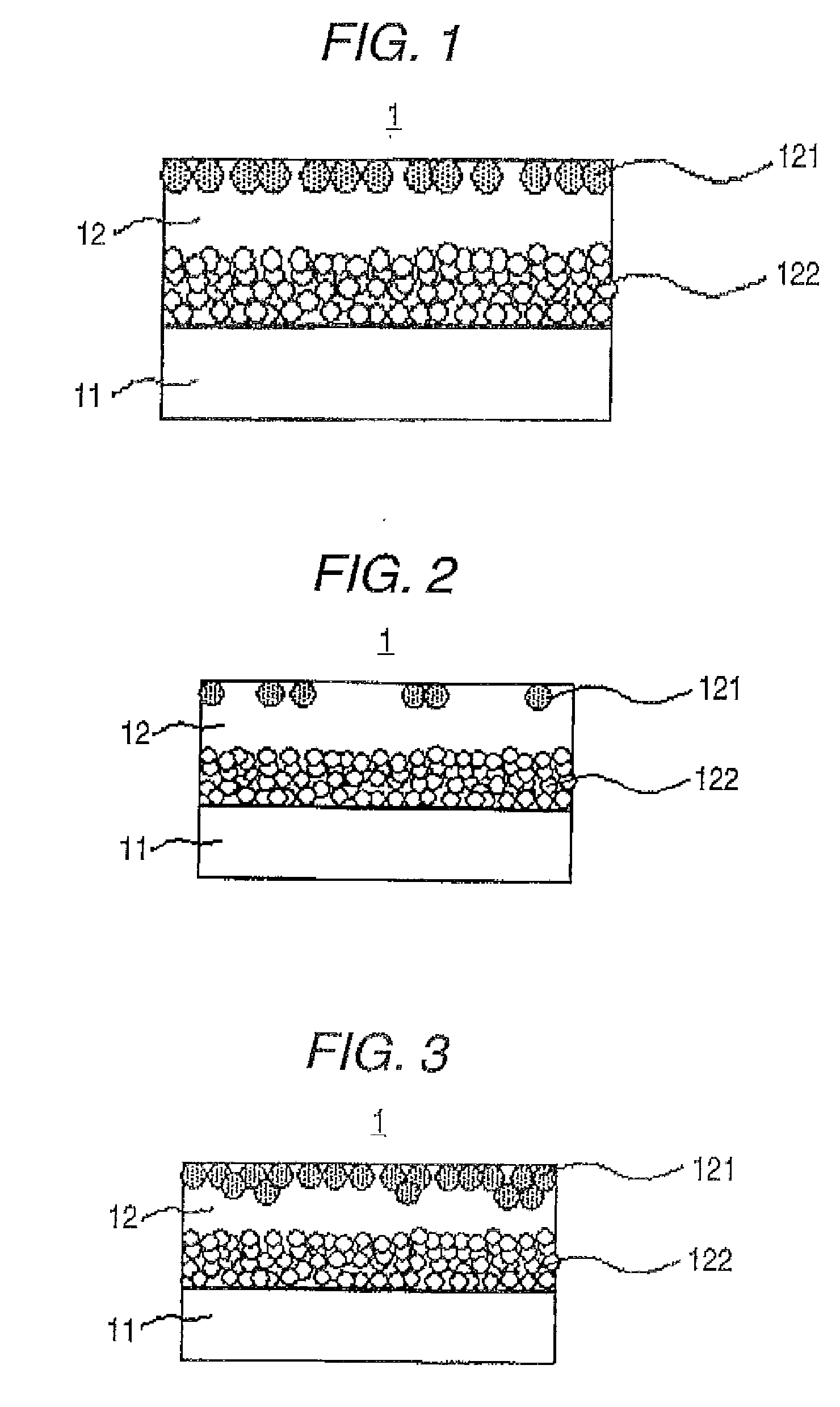
Image

Examples
example 1
Preparation of Optical Film
(Preparation of Optical Film 1-1A)
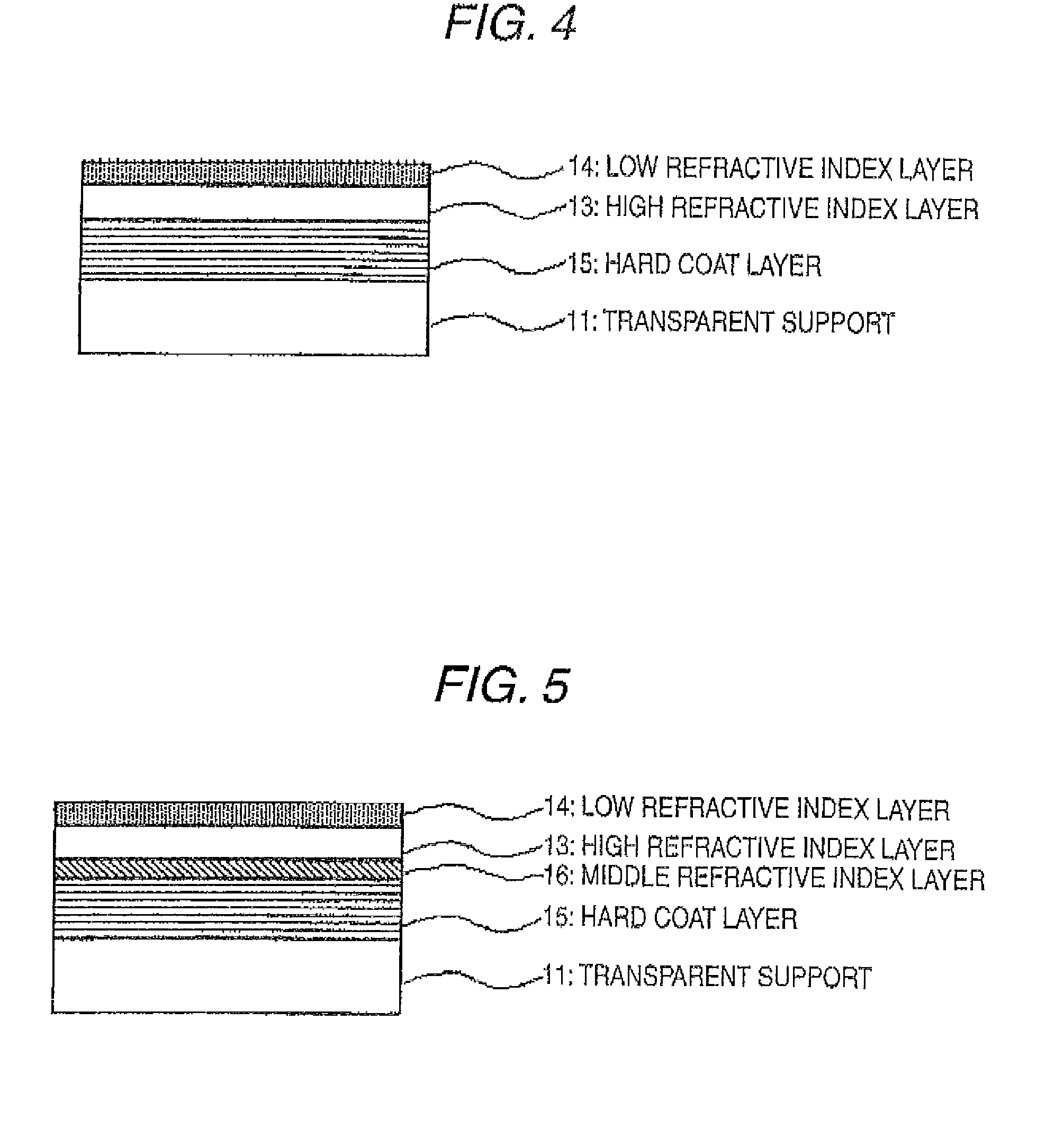
[0330]The foregoing coating solution A for hard coat layer was coated on a triacetyl cellulose film having a thickness of 80 μm (TAC-TA80U, manufactured by FUJIFILM Corporation; refractive index: 1.49) using a slot die coater (the coater as shown in FIG. 3(A) of JP-A-2007-293313) and dried at 100° C. for 2 minutes. Subsequently, purge with nitrogen was carried out, and ultraviolet rays were irradiated at 70 mJ / cm2 under a condition in an oxygen concentration of 0.1% to cure the coated layer, thereby forming a hard coat layer (refractive index: 1.50, thickness: 6 μm). Subsequently, the foregoing coating composition A for middle refractive index layer was coated using a slot die coater (the coater as shown in FIG. 3(A) of JP-A-2007-293313) and dried at 100° C. Thereafter, purge with nitrogen was carried out, and ultraviolet rays were irradiated at 200 mJ / cm2 under a condition in an oxygen concentration of 0.1% to cure the co...
example 2
Preparation of Optical Film
(Preparation of Optical Films 2-4A, 2-1B and 2-1D)
[0365]Optical films 2-1A, 2-1B and 2-1D were each prepared in the same manner as in the optical film 1-1A, except for using the coating solution B for hard coat layer as the coating solution for hard coat layer and using the coating solutions A, B and D for optical functional layer, respectively as the coating solution for optical functional layer.
[0366]In 2-1A, 2-1B and 2-1D each using the coating solution B for hard coat layer to which E crosslinked poly(acryl-styrene) particle having an average particle size of 3.5 μm had been added, satisfactory antireflection properties and scratch resistance were found, and the antireflection properties were more improved than those in 1-1A, 1-1B and 1-1D due to the antiglare function. In particular, the integrated reflection of 2-1A was low as 0.30% so that excellent antireflection properties were exhibited together with the antiglare properties.
(Saponification Treat...
example 3
Preparation of Optical Film
(Preparation of Optical Films 3-1A, 3-1B and 3-1D)
[0369]Optical films 3-1A, 3-1B and 3-1D were each prepared in the same manner as in the optical film 1-1A, except for not using the middle refractive index layer and using the coating solutions A, B and D for each of optical functional layers as the coating solutions for each of optical functional layers, respectively.
[0370]Even in the case of not providing the middle refractive index layer on the hard coat layer, in 3-1A, 3-1B and 3-1D, satisfactory antireflection properties and scratch resistance were found. 3-1A had a low reflection as 0.50% and exhibited excellent antireflection properties even in a two-layer type optical film,
(Saponification Treatment of Optical Film and Preparation of Polarizing Plate)
[0371]A saponification treatment and polarizing plate preparation were carried out in the same manners as in 1-2A, except for using each of 3-1A, 3-1B and 3-1D as the optical film sample, thereby prepari...
PUM
| Property | Measurement | Unit |
|---|---|---|
| thickness | aaaaa | aaaaa |
| thickness | aaaaa | aaaaa |
| refractive index | aaaaa | aaaaa |
Abstract
Description
Claims
Application Information