
Negative electrode for nonaqueous secondary battery

a secondary battery and negative electrode technology, applied in the field of negative electrodes for nonaqueous secondary batteries, can solve the problems of battery cycle life reduction, reduce the effect of metallic materials, etc., and achieve the effect of low formability

Inactive Publication Date: 2009-08-13
MITSUI MINING & SMELTING CO LTD
View PDF4 Cites 54 Cited by
  • Summary
  • Abstract
  • Description
  • Claims
  • Application Information

AI Technical Summary

Benefits of technology

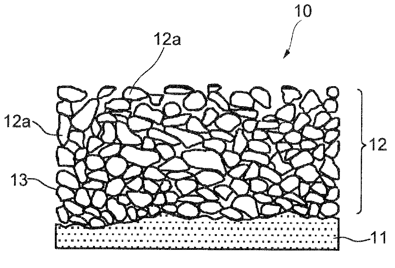
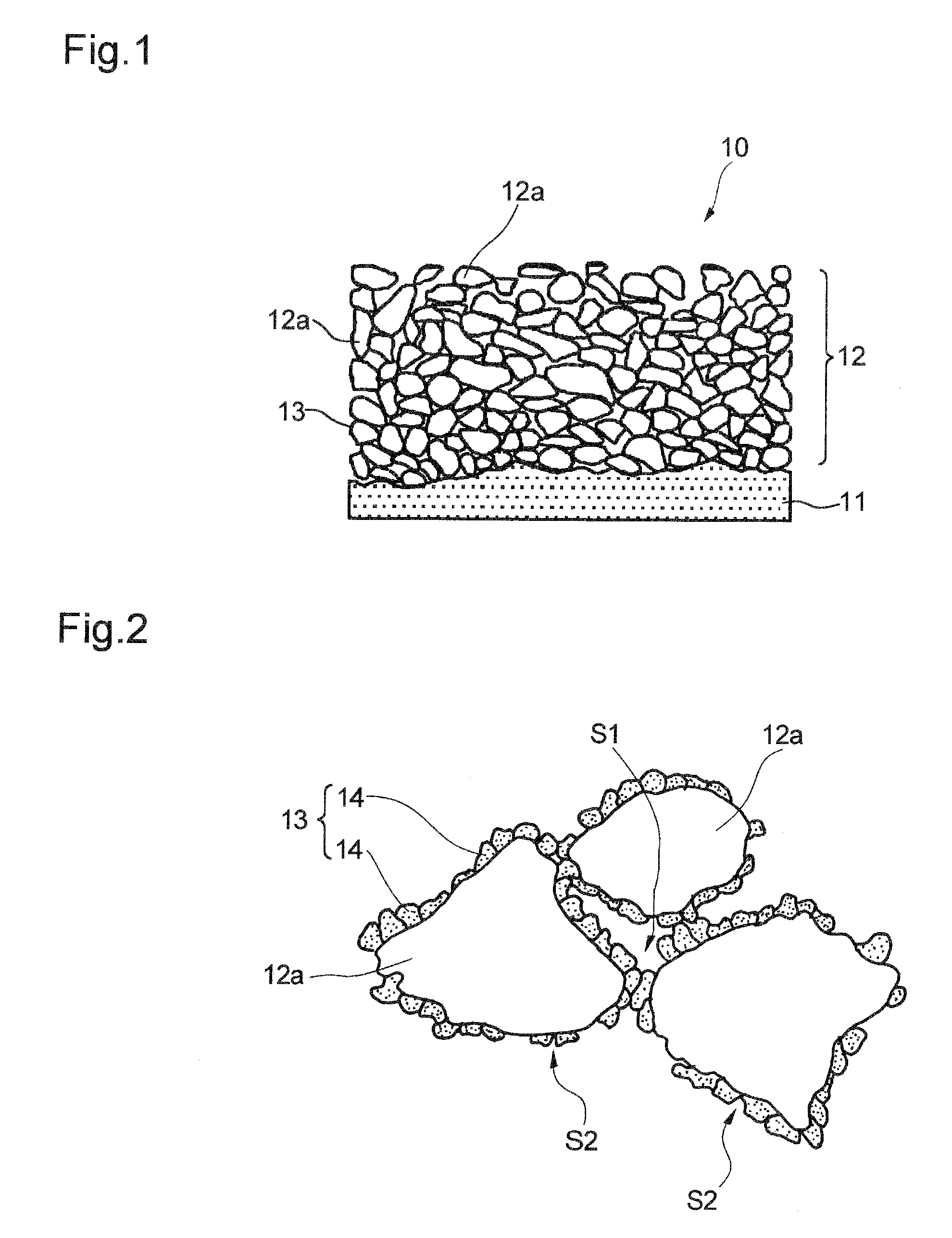
The invention is about a new type of negative electrode for a nonaqueous secondary battery. The electrode has a layer of active material that contains particles of active material that are coated with a thin layer of metallic material. These particles are separated by voids in the layer. The layer has a certain percentage of voids, which can be measured using a mercury porosimeter. The technical effect of this invention is to improve the performance of nonaqueous secondary batteries by improving the structure of the negative electrode.

Problems solved by technology

Nevertheless, formation of too many flow passages reduces the effect of the metallic material in holding the particulate active material, which can allow the active material particles pulverized as a result of expansion and contraction accompanying charge and discharge cycles to fall off.
Conversely, where formation of the flow passages is insufficient, the lithium ions are hardly allowed to reach inside the active material layer, and it would be limited to the active material particles existing on, and in the vicinity of, the surface of the active material layer that can take part in electrode reaction.
As a result, the battery will have a reduced cycle life.

Method used


Image

  • Negative electrode for nonaqueous secondary battery
  • Negative electrode for nonaqueous secondary battery
  • Negative electrode for nonaqueous secondary battery

Examples


example 1

[0072]A 18 μm thick electrolytic copper foil as a current collector was cleaned with an acid at room temperature for 30 seconds and washed with pure water for 15 seconds. A slurry of Si particles was applied to the current collector to a thickness of 15 μm to form a coating layer. The slurry contained the particles, styrene-butadiene rubber (binder), and acetylene black at a weight ratio of 100:1.7:2. The particles had an average particle size D50 of 2.5 μm and a particle size distribution D10 / D90 of 0.07. The average particle size D50 and particle size distribution D10 / D90 were measured using a laser diffraction scattering particle size analyzer Microtrack (Model 9320-X100) from Nikkiso Co., Ltd. The Si particles were found to be single crystals as observed by Pegasus System from EDAX.

[0073]The current collector having the coating layer was immersed in a copper pyrophosphate plating bath having the following composition, and the coating layer was penetration-plated with copper by e...

examples 2 to 5

[0082]A negative electrode was fabricated in the same manner as in Example 1, except for using Si single crystal grains having the average particle size D50 and particle size distribution D10 / D90 shown in Table 1 below as Si particles.


PUM

PropertyMeasurementUnit
particle sizeaaaaaaaaaa
pressureaaaaaaaaaa
pressureaaaaaaaaaa

Abstract

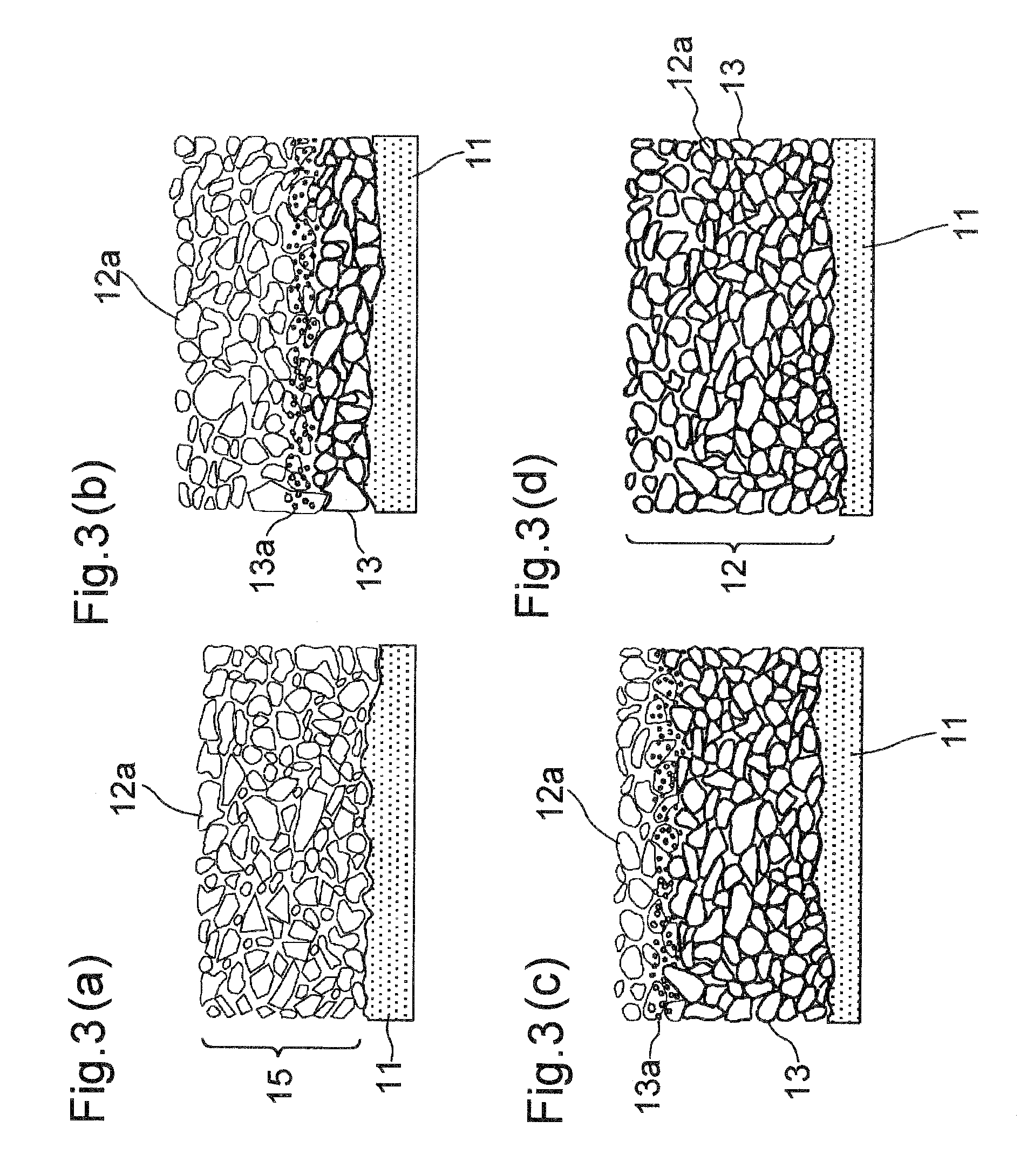
A negative electrode (10) for use in a non-aqueous electrolyte secondary battery comprises an active material layer (12) containing a particle (12a) of an active material. At least a part of the surface of the particle (12a) is coated with a metal material (13) having a poor ability of forming a lithium compound. A void is formed between the particles (12a) that are coated with the metal material (13). The active material layer has a void ratio of 15 to 45%. Preferably, the metal material (13) is present over the entire area of such a part of the surface of the particle that extends in the thickness-wise direction of the active material layer. Also preferably, the particle (12a) of the active material is composed of a silicone material, and the active material layer (12) contains a conductive carbon material in an amount of 1 to 3% by weight relative to the weight amount of the particle (12a) of the active material.

Description

TECHNICAL FIELD[0001]This invention relates to a negative electrode for a nonaqueous secondary battery.BACKGROUND ART[0002]Assignee of the present invention previously proposed in Patent Document 1 a negative electrode for a nonaqueous secondary battery having a pair of current collecting surface layers of which the surfaces are brought into contact with an electrolyte and an active material layer interposed between the surface layers. The active material layer contains a particulate active material having high capability of forming a lithium compound. A metallic material having low capability of forming a lithium compound is present over the whole thickness of the active material layer such that the active material particles exist in the penetrating metallic material. Owing to the structure of the active material layer, even if the active material particles pulverize as a result of repeated expansion and contraction accompanying charge and discharge cycles, there is less likelihood...

Claims


Application Information

Patent Timeline
Patent Type & Authority Applications(United States)
IPC IPC(8): H01M2/16H01M4/02H01M4/133H01M4/134H01M4/1395H01M4/485H01M10/0566
CPCH01M4/134H01M4/38Y02E60/122H01M10/0525H01M2004/021H01M4/625H01M4/386Y02E60/10H01M4/13H01M10/05C25D5/18C25D5/623
Inventor MODEKI, AKIHIROMATSUSHIMA, TOMOYOSHIHYAKUTAKE, MASAHIROYASUDA, KIYOTAKASHINZAWA, KAYOKOSAKAGUCHI, YOSHIKI
Owner MITSUI MINING & SMELTING CO LTD
Learn More