Endoscope light source device

Inactive Publication Date: 2009-08-13
FUJIFILM CORP
View PDF17 Cites 68 Cited by
  • Summary
  • Abstract
  • Description
  • Claims
  • Application Information

AI Technical Summary

Benefits of technology

[0021]According to the present invention, the light beam emitted from a single semiconductor light source or plural semiconductor light sources is guided by a plurality of independent optical fibers in at least the angle portion of the endoscope, and the optical fibers are coupled together on the distal end side with respect to the angle portion (bending portion) of the endoscope insertion section, with the light beams from the light source or sources being coupled together and emitted to the illumination portion. With the above-mentioned configuration, even when one of the optical fibers is disconnected halfway, safe use of the endoscope can be ensured without stopping the illumination light.
[0022]Further, according to an embodiment of the present invention, the ligh

Problems solved by technology

However, when the light guide is branched inside the endoscope, there arises a problem in that buckling or disconnection is likely to occur in the branch portion of the light guide upon bending of the endoscope.
However, in the conventional light guide, a large number of, such as one thousand, optical fibers are bundled into the light guide, and hence some of the optical fibers are damaged even in a portion other than the branched portion discussed as a problem in JP 07-246186 A, due to frictions among the optical fibers or difference in tension between the inner curve and the outer curve of a bent fiber in the bending portion or the like, thereby reducing the number of effective optical fibers in use for a long period of time.
For that reason, the optical output from the illumination portion is gradually deteriorated.
Further, the endoscope using the conventional light guide has problems in that it is very difficult to reduce the diameter of the

Method used


Image

  • Endoscope light source device
  • Endoscope light source device
  • Endoscope light source device

Examples


Example

[0032]First, a first embodiment of the present invention is described.

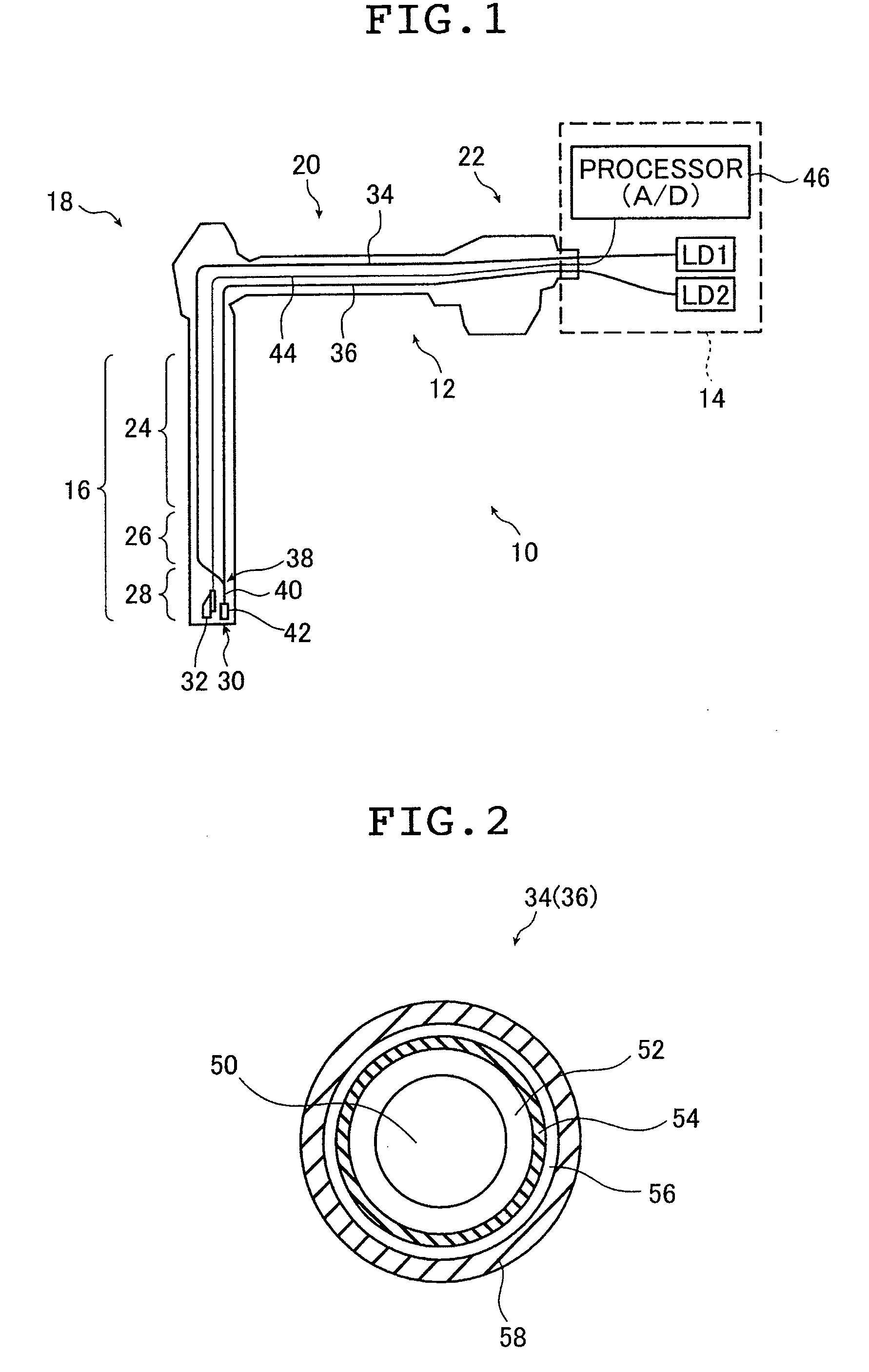
[0033]FIG. 1 is a schematic diagram illustrating a first example of an endoscope system using an endoscope lighting device according to the present invention. An endoscope system 10 illustrated in FIG. 1 includes an endoscope 12 and a control device 14. In FIG. 1, the endoscope 12 is illustrated with a schematic cross-sectional diagram, and an image optical system arrangement and an optical path inside the endoscope 12 are illustrated.

[0034]The endoscope 12 is a so-called electronic endoscope that has a compact television camera (CCD) at a distal end thereof, and transmits acquired image information to the control device 14 as an electric signal.

[0035]The control device 14 includes two semiconductor laser light sources (semiconductor light emitting elements) LD1 and LD2, and a processor 46. The processor 46 converts an electric signal (imaging signal) that has been transmitted from the endoscope 12 into a digital ...

Example

[0059]Subsequently, a second embodiment of the present invention is described.

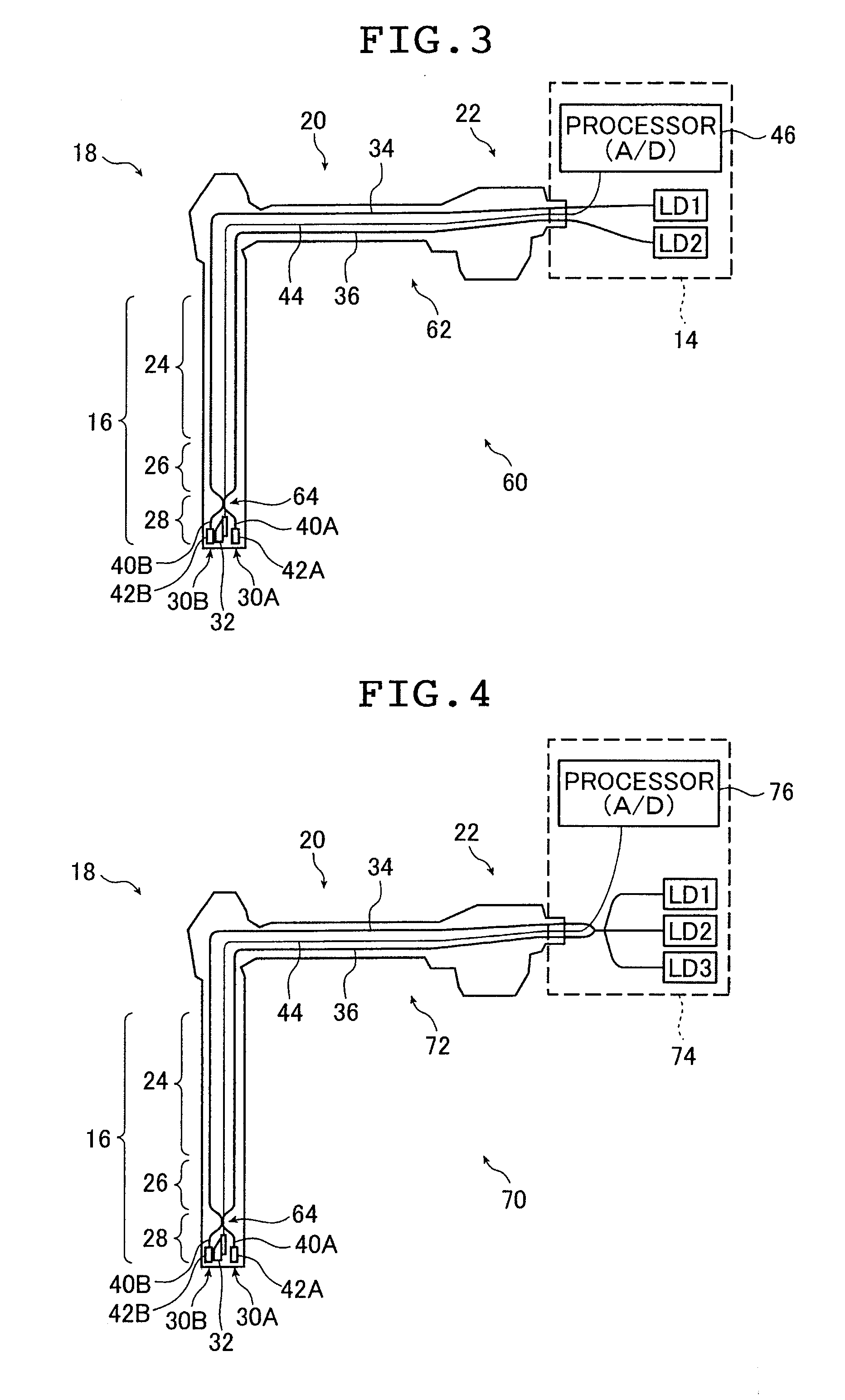
[0060]FIG. 3 is a schematic diagram illustrating a second example of an endoscope system using an endoscope lighting device according to the present invention. An endoscope system 60 illustrated in FIG. 3 emits illumination light beams from two points at the distal end of the endoscope 62.

[0061]In many of existing general endoscopes, illumination light beams are emitted from two points at the distal end of the endoscope in order to prevent an oversight due to illumination unevenness or shadow within the field of view. The endoscope system 60 provides such a two-lighting type endoscope light source device.

[0062]The endoscope system 60 is identical in configuration with the endoscope system 10 described above with reference to FIG. 1 except for the configuration of the distal end portion 28 of the endoscope 62. In FIG. 3, the same components as those of the endoscope system 10 of FIG. 1 are denoted by identi...

Example

[0069]Next, a third embodiment of the present invention is described.

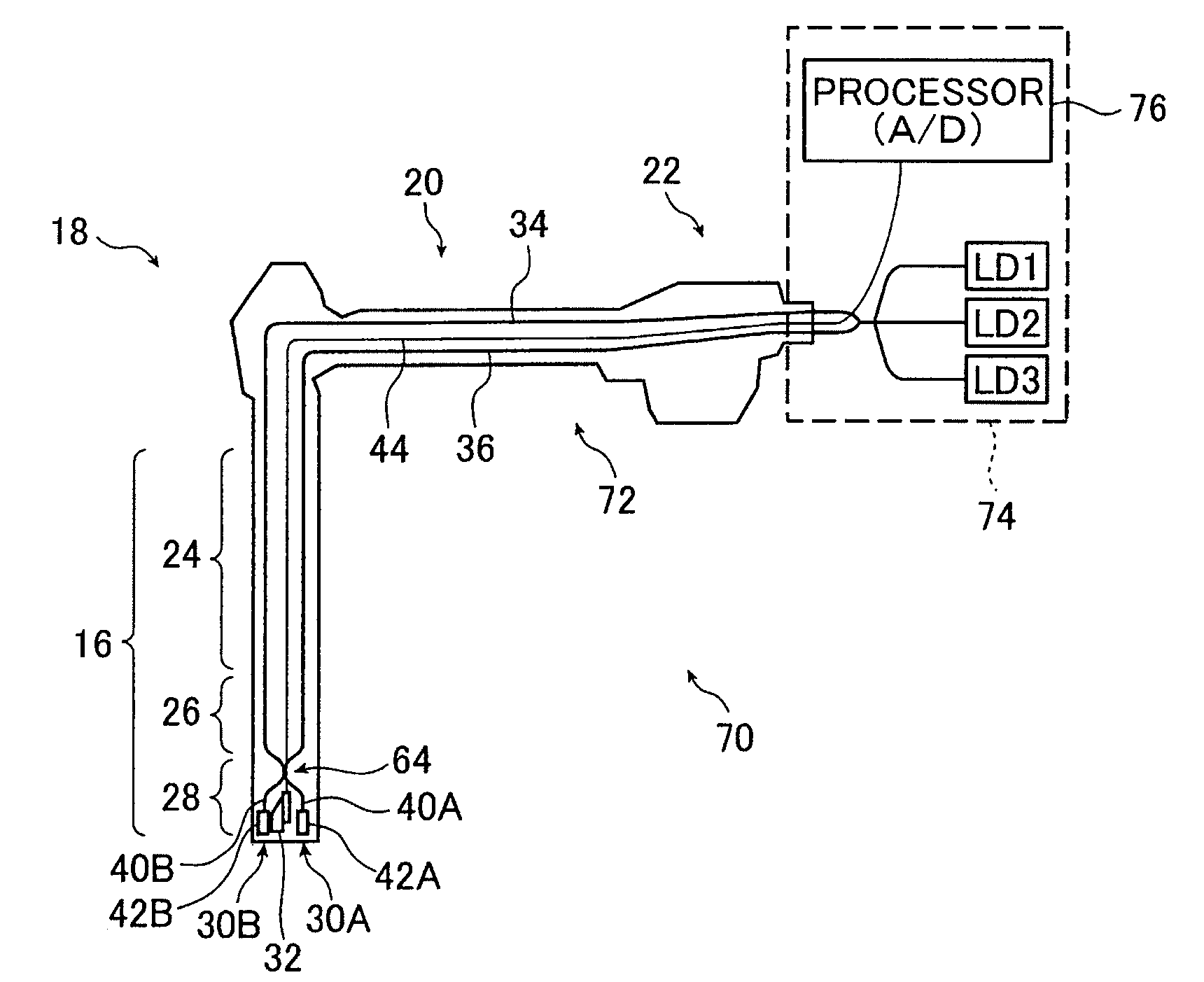
[0070]FIG. 4 is a schematic diagram illustrating a third example of an endoscope system using an endoscope lighting device according to the present invention. An endoscope system 70 illustrated in FIG. 4 includes an endoscope 72 and a control device 74. The endoscope 72 is of the same configuration as that of the endoscope 62 in the endoscope system 60 of FIG. 3, and emits two illumination light beams from the distal end. The control device 74 is different from the control device 14 in the endoscope system 60 of FIG. 3 in that three semiconductor laser light sources are provided.

[0071]When three or more semiconductor laser light sources LDs are provided, one optical fiber may be connected to each of the light sources so as to cause the optical fibers to guide light up to the distal end portion of the endoscope 72. However, the optical coupling / branching circuit 64 becomes larger in size as the number of optical fib...


PUM


Abstract

The endoscope light source device includes a semiconductor light source, optical fibers that are inserted into an endoscope, guide first light beams from the semiconductor light source, and are arranged in plural rows in at least an angle portion of the endoscope, an optical coupling circuit that is arranged at a distal end side of the endoscope with respect to the angle portion, and couples the first light beams guided by the optical fibers arranged in the plural rows to obtain a coupled light beam and a wavelength conversion part that is arranged at a distal end side of an endoscope insertion section in the optical coupling circuit, and converts a part or all of the coupled light beam from the optical coupling circuit into a converted light beam having a given wavelength by a phosphor.

Description

[0001]The entire contents of all documents cited in this specification are incorporated herein by reference.BACKGROUND OF THE INVENTION[0002]The present invention relates to an endoscope light source device.[0003]An endoscope has an insertion section, which is inserted into the living body such as the human body, and is used for diagnosis or treatment of organs, collection of specimens, and so forth. The distal end of the insertion section of the endoscope is provided with an imaging element for acquiring an image, and an output window for an illumination light for illuminating an observed region. A light guide formed of a bundle of optical fibers is inserted into the endoscope, and is connected to a white light source such as a xenon lamp to transmit a light from the light source to the distal end of the insertion section.[0004]As an endoscopic illumination method, a method is known in which the light beams emitted from two points at the distal end of an endoscope are used to illum...

Claims


Application Information

Patent Timeline
IPC IPC(8): A61B1/07
CPCA61B1/00096A61B1/0017A61B1/04A61B1/0638A61B1/07G02B23/26A61B1/0653
Inventor MIZUYOSHI, AKIRA
Owner FUJIFILM CORP
Why Eureka
Try Eureka