Low-pressure gas discharge lamp having improved efficiency

a efficiency-enhancing technology, which is applied in the direction of low-pressure discharge lamps, discharge tube luminescnet screens, discharge tube main electrodes, etc., can solve the problems of reducing the efficiency of the known reducing the efficiency of low-pressure mercury vapor discharge lamps, and limited life of luminescent materials used to generate uv-a and uv-b. , to achieve the effect of improving efficiency

Inactive Publication Date: 2009-08-20
KONINKLIJKE PHILIPS ELECTRONICS NV
View PDF8 Cites 5 Cited by
  • Summary
  • Abstract
  • Description
  • Claims
  • Application Information

AI Technical Summary

Benefits of technology

[0005]It is an object of the invention to provide a low-pressure gas discharge lamp with improved efficiency.
[0007]The effect of the measures according to the invention is that the presence of the metal compound selected from the group formed by compounds of titanium, zirconium, hafnium, and their mixtures, results in an emission of light from the discharge space, of which part is in the visible range of the electromagnetic spectrum. In the discharge space of the low-pressure gas discharge lamp according to the invention, a gas discharge takes place at a low pressure. Apart from the characteristic lines of titanium, zirconium and / or hafnium atoms, the emitted light further includes a contribution from different compounds of titanium, zirconium and / or hafnium, such as chlorides, bromides, iodides and / or, for example, oxy-iodides, which are present in the discharge space, resulting in a substantially continuous spectrum of light. Part of the continuous spectrum is in the visible range. In the known low-pressure mercury vapor discharge lamps, the main emission of light is in the ultraviolet region (wavelength of the main ultraviolet light emission in the known low-pressure mercury vapor discharge lamp is at approximately 254 nanometer). To produce visible light from these known low-pressure mercury vapor discharge lamps, luminescent materials are used. The luminescent materials convert the emitted ultraviolet light into visible light. During this conversion, energy is lost which reduces the efficiency of the known low-pressure mercury vapor discharge lamps. The low-pressure gas discharge lamp according to the invention produces visible light without the need for luminescent materials, which improves the efficiency.
[0014]In an embodiment of the low-pressure gas discharge lamp, the low-pressure gas discharge lamp comprises an outer vessel enclosing the discharge vessel. A benefit of the additional outer vessel is that it provides additional thermal insulation, which further reduces the energy loss from loss of heat. Furthermore, a luminescent layer may conveniently be applied at the inside of the outer vessel, preventing the luminescent material to react with the gas filling inside the discharge vessel.
[0016]In an embodiment of the low-pressure gas discharge lamp, the low-pressure gas discharge lamp comprises elements which maintain the discharge via inductive operation, further also referred to as inductive coupler. The elements may also maintain the discharge via capacitive operation, microwave operation, or via electrodes. A benefit of such a, so called electrodeless low-pressure gas discharge lamp is that the average lifetime of the electrodeless low-pressure gas discharge lamp is considerably longer compared to conventional low-pressure gas discharge lamps which have electrical contacts through the discharge vessel to transfer power into the discharge space. Generally, the electrical contacts, also referred to as electrodes, limit the lifespan of the conventional low-pressure gas discharge lamps. The electrodes may, for example, become contaminated with residue or, for example, get damaged by the discharge and cannot transfer sufficient power into the discharge space to guarantee operation of the conventional low-pressure gas discharge lamp. Providing the low-pressure gas discharge lamp with an inductive coupler according to the invention considerably increases the lifetime of the low-pressure gas discharge lamp. An example of such an inductive coupler is a coil which is, for example, arranged around the light-transmitting discharge vessel, or which is, for example, arranged in a glass protrusion, protruding into the discharge vessel. The inductive coupler may also be used, apart from to maintain the discharge, to generate the discharge in the discharge vessel of the low-pressure gas discharge lamp according to the invention.
[0017]In a preferred embodiment of the low-pressure gas discharge lamp, the discharge vessel comprises a luminescent layer comprising a luminescent material. The luminescent material, for example, absorbs part of the ultraviolet light emitted by the compounds of titanium, zirconium, hafnium, and / or their mixtures, and converts the absorbed ultraviolet light into visible light. When the low-pressure gas discharge lamp according to the invention is used for general illumination purposes, the low-pressure gas discharge lamp should produce substantially white light at the required color temperature. Due to the added titanium compounds, zirconium compounds and / or hafnium compounds, part of the light emitted by the low-pressure gas discharge lamp is in the visible range of the electromagnetic spectrum. Altering the gas-pressure and / or operating temperature inside the discharge vessel induces a change of the spectrum of the emitted light and hence also of the color of the light emitted by the low-pressure gas discharge lamp according to the invention. However, the required color temperature of the low-pressure gas discharge lamp may not be achieved by only altering the gas-pressure and / or operating temperature. Adding a luminescent layer comprising luminescent materials enables the light emitted by the luminescent material to be mixed with the light emitted from the discharge space to produce the required color temperature. Examples of commonly used luminescent materials are, for example, a blue-luminescent europium-activated barium magnesium aluminate, BaMgAl10O17:Eu2+ (also referred to as BAM) and a red-luminescent europium-activated yttrium oxysulfide, Y2O2S:Eu (also referred to as YOS). Although luminescent materials are used in this preferred embodiment to adapt the color of the emitted light from the low-pressure gas discharge lamp, the efficiency of the low-pressure gas discharge lamp is still higher compared to conventional low-pressure mercury vapor discharge lamps. The ultraviolet part of the light emitted by the low-pressure gas discharge lamp according to the invention is in the near ultraviolet range, which comprises a substantially longer average wavelength compared to the main ultraviolet emission of the mercury vapor (which is around 254 nanometer). This shift of the average wavelength of the ultraviolet part of the emitted light in the low-pressure gas discharge lamps according to the invention to longer wavelengths results in a reduced Stokes shift, because the difference between the average energy of the ultraviolet photon which is absorbed by the luminescent material and the average energy of the emitted photon in the visible range is reduced, resulting in a reduction of the losses. Part of the light emitted from the discharge space of the low-pressure gas discharge lamp according to the invention is in the visible range of the electromagnetic spectrum, which already improves the efficiency of the low-pressure gas discharge lamp according to the invention with respect to the conventional low-pressure mercury vapor discharge lamps. The luminescent layer comprising the luminescent material may be applied to the inside or to the outside of the discharge vessel. Applying the layer comprising a luminescent material to the outside of the discharge vessel prevents the luminescent material from reacting with the gas filling inside the discharge vessel.
[0018]In an embodiment of the low-pressure gas discharge lamp, the discharge vessel comprises a coating for thermal insulation. Generally, the operating temperature of the low-pressure discharge lamps according to the invention is higher compared to conventional low-pressure mercury vapor discharge lamps to ensure that enough metal vapor is in the gas filling. The additional coating for thermal insulation may be an infrared radiation-reflecting coating reflecting the emitted infrared radiation from the discharge space back into the discharge space. The result of the added infrared radiation-reflecting coating is an increase in temperature inside the discharge vessel. Alternatively, the coating for thermal insulation may form a shield between the increased temperature inside the discharge vessel and the outside of the discharge vessel and as such shield a user handling the low-pressure gas discharge lamps from the increased temperature.

Problems solved by technology

During this conversion, energy is lost which reduces the efficiency of the known low-pressure mercury vapor discharge lamps.
However, a drawback of the known UV-generating low-pressure mercury vapor discharge lamp is that the luminescent materials used to generate UV-A and UV-B have a limited lifetime due to a relatively strong degradation of the luminescent materials.

Method used


Image

  • Low-pressure gas discharge lamp having improved efficiency
  • Low-pressure gas discharge lamp having improved efficiency
  • Low-pressure gas discharge lamp having improved efficiency

Examples


Embodiment Construction

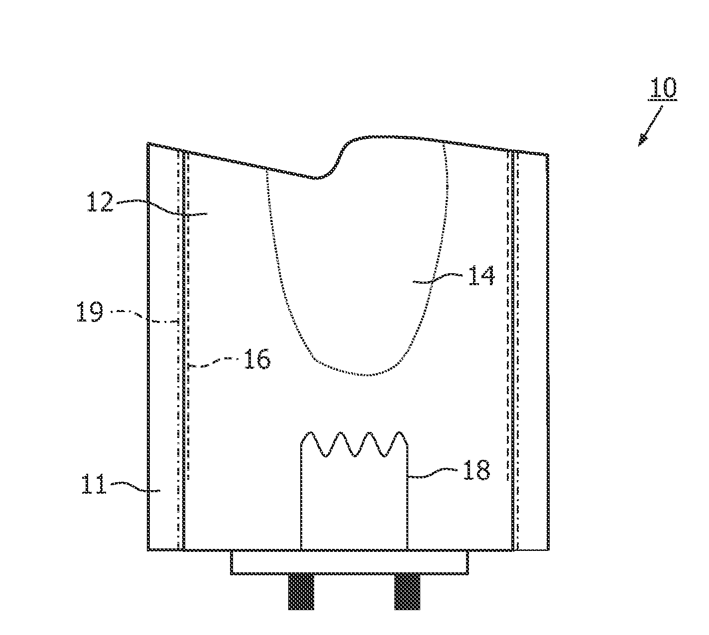
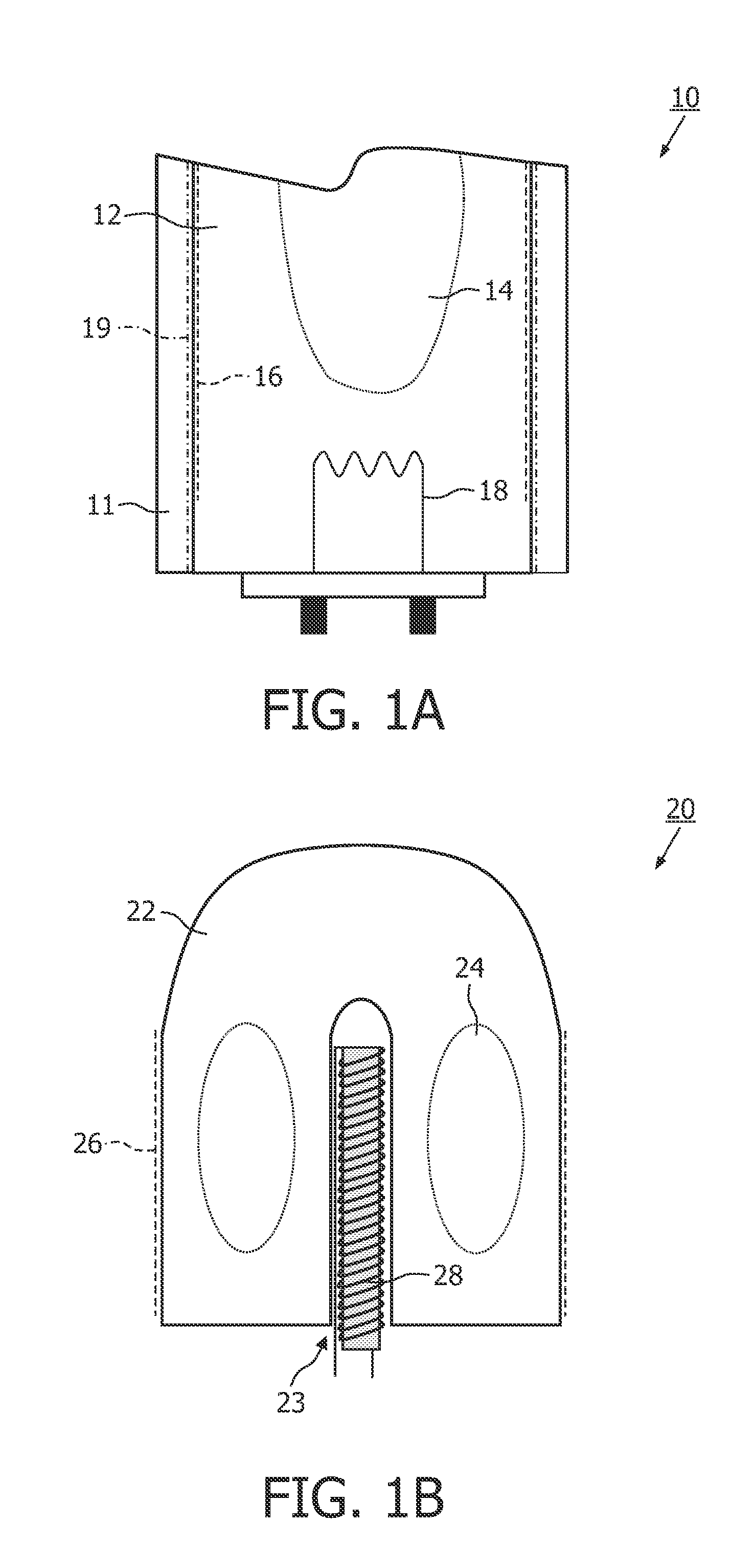
[0030]FIGS. 1A and 1B show a cross-sectional view of a low-pressure gas discharge lamp 10, 20 according to the invention. The low-pressure gas discharge lamp 10, 20 according to the invention comprises a light transmitting discharge vessel 12, 22 which encloses a discharge space 14, 24 in a gastight manner. The discharge space 14, 24 comprises a gas filling, for example, comprising a metal compound and a buffer gas. The low-pressure gas discharge lamp 10, 20 further comprises coupling elements 18, 28. The coupling elements, for example, couple energy into the discharge space 14, 24 via capacitive coupling, inductive coupling, microwave coupling, or via electrodes to obtain a gas discharge in the discharge space 14, 24.

[0031]In an embodiment shown in FIG. 1A the discharge elements 18 are a set of electrodes 18. In FIG. 1A only one electrode 18 of the set of electrodes 18 is shown. The electrodes 18 are electrical connections through the discharge vessel 12 of the low-pressure gas dis...


PUM


Abstract

The invention relates to a low-pressure mercury vapor discharge lamp (10) comprising a metal compound which is selected from the group formed by compounds of titanium, zirconium, hafnium and their mixtures. The effect of adding the metal compound selected from said group to the gas filling of the discharge space (14) results in an increased efficiency of the low-pressure gas discharge lamp (10), because part of the emitted light from the discharge space (14) is in the visible range of the electromagnetic spectrum. In one embodiment of the invention, the low-pressure gas discharge lamp (10) produces substantially white light without the use of a luminescent layer (16) comprising a luminescent material. In another embodiment of the invention, the luminescent layer (16) is applied to the discharge vessel (12) of the low-pressure gas discharge lamp (10). The light emitted by the luminescent material can be mixed with the light emitted from the discharge space (14) to produce the required color.

Description

FIELD OF THE INVENTION[0001]The invention relates to a low-pressure gas discharge lamp.BACKGROUND OF THE INVENTION[0002]Low-pressure gas discharge lamps generally comprise mercury as a primary component for the generation of ultraviolet (further also referred to as UV) light. A luminescent layer comprising a luminescent material may be present on an inner wall of a discharge vessel to convert UV light into light of increased wavelength, for example, into UV-C for medical purposes, UV-B and UV-A for tanning purposes (sun tanning lamps) or into visible radiation for general illumination purposes. Such discharge lamps are therefore also referred to as fluorescent lamps. Fluorescent lamps for general illumination purposes usually comprise a mixture of luminescent materials, which determines the color of the light emitted by the fluorescent lamps. Examples of commonly used luminescent materials are, for example, a blue-luminescent europium-activated barium magnesium aluminate, BaMgAl10O1...

Claims


Application Information

Patent Timeline
Patent Type & Authority Applications(United States)
IPC IPC(8): H01J61/12H01J61/52H01J1/62
CPCA61L2/10A61L9/20H01J65/042H01J61/125H01J61/70C02F1/32
Inventor ANTONIS, PIETDE GRAAF, ARIELKITSINELIS, SPYRIDONVANKAN, PETER JOHANNES WILHELMUS
Owner KONINKLIJKE PHILIPS ELECTRONICS NV
Why Eureka
Try Eureka