Antiferroelectric multilayer ceramic capacitor

a ceramic capacitor and antiferroelectric technology, applied in the field of ceramic capacitors, can solve the problems of high energy density, high voltage, and large capacity of energy storage capacitors, and achieve the effect of high energy density and antiferroelectric materials

Inactive Publication Date: 2009-08-20
TRS TECH
View PDF6 Cites 35 Cited by
  • Summary
  • Abstract
  • Description
  • Claims
  • Application Information

AI Technical Summary

Benefits of technology

[0040]The powder mixture includes a raw material powder, a solvent; and pH adjusters. The raw material powder includes about stoichiometr

Problems solved by technology

The main limitation to improving these systems either by delivering more energy or by reducing their size, particularly on mobile platforms, is the capacity and size of the energy storage capacitors.
Capacitors that can be made with thin, high quality dielectric and low resistivity electrodes can be operated with a high electric field across the dielectric resulting in high voltage and therefore high energy density.
However, they have low melting temperatures so they cannot usually be used much higher than 100° C. Also for power conditioning applications, where the capacitors are subjected to high frequency signals for long periods of time, the operating voltages must be significantly derated from what would be used in pulse power applications.
However, the quality of current polymer films is very high, and there are few areas of polymer capacitor manufacturing technology that can be improved to further increase breakdown strength.
There have been many recent attempts to improve polymers by increasing dielectric constant, but this often results in reduced temperature ranges and increased loss.
Unfortunately, the electrolyte cathode results in very high losses, and a lot of capacitors must be connected in parallel to prevent overheating in high frequency power conditioning.
For pulse power applications the losses limit how fast the capacitor can be discharged.
They are also limited in temperature to about 80 to 100° C. due to conduction effects and reliability concerns, and aluminum capacitors can not be made to operate above 500V due to limitations in how thick the dielectric layer can be.
This results in lower energy density than would be expected from low field measurements of capacitance.
However, unlike polymers this energy density can be achieved in both pulse and power conditioning applications because ceramics have relatively low losses and much greater temperature stability than polymers.
Ceramics find wide use in power conditioning applications, but are used less in pulse power applications because they are more expe

Method used


Image

  • Antiferroelectric multilayer ceramic capacitor
  • Antiferroelectric multilayer ceramic capacitor
  • Antiferroelectric multilayer ceramic capacitor

Examples


Embodiment Construction

[0057]The present invention now will be described more fully hereinafter with reference to the accompanying drawing, in which a preferred embodiment of the invention is shown. This invention may, however, be embodied in many different forms and should not be construed as limited to the embodiments set forth herein; rather, these embodiments are provided so that this disclosure will be thorough and complete and will fully convey the scope of the invention to those skilled in the art.

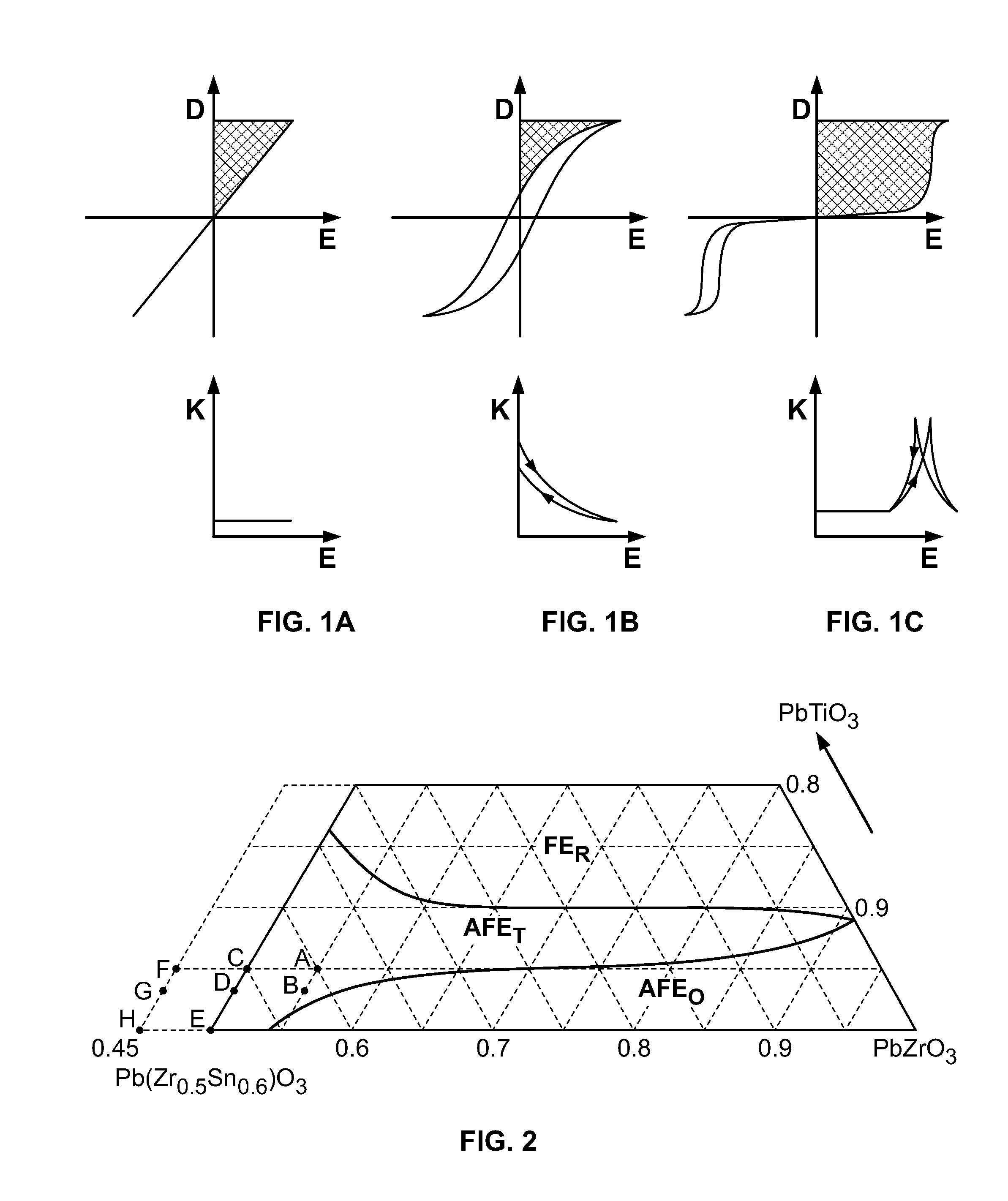
[0058]The invention makes use of a class of materials known as antiferroelectrics which are ceramics that exhibit high breakdown strengths and dielectric permittivities that increase with electric field. This is in contrast to polymers, electrolytics, mica, supercapacitors, glass, and many types of ceramic capacitors all of which make use of linear dielectrics. These have dielectric permittivities that do not change value with applied field. An exception is ceramic capacitors with high dielectric constant...


PUM

PropertyMeasurementUnit
Temperatureaaaaaaaaaa
Lengthaaaaaaaaaa

Abstract

An antiferroelectric ceramic material that can be formed into a multilayer capacitor is disclosed. The antiferroelectric ceramic material is selected from the Pb(Sn, Zr, Ti)O3 (PSnZT) composition family.

Description

FIELD OF THE INVENTION[0001]The present invention is directed to ceramic capacitors, and more specifically to multilayer ceramic capacitors containing antiferroelectric material.BACKGROUND OF THE INVENTION[0002]Power electronics are becoming increasingly important to applications such as power distribution, transportation, spacecraft, medical devices, and weapons. Modern power electronics use solid state switching devices to convert AC to DC and to change voltages and waveforms. The electronics are most often computer programmable and can be used to rapidly change the type of power delivered in response to changing demands. On large and medium size transportation platforms such as ships, submarines, aircraft, and hybrid electric vehicles, electric drive systems are replacing direct mechanical linkages, such as drive shafts, resulting in highly efficient and adaptable propulsion systems. Advanced power electronics are also making it possible to reroute power on demand from electric m...

Claims


Application Information

Patent Timeline
IPC IPC(8): H01G4/12H01G7/04
CPCC04B35/493Y10T29/435C04B35/6263C04B35/6264C04B35/632C04B35/6455C04B2235/3208C04B2235/3213C04B2235/3215C04B2235/3224C04B2235/3225C04B2235/3227C04B2235/3229C04B2235/3239C04B2235/3241C04B2235/3267C04B2235/3275C04B2235/3279C04B2235/3293C04B2235/3296C04B2235/365C04B2235/5409C04B2235/5445C04B2235/6025C04B2235/604C04B2235/661C04B2235/768C04B2235/77H01G4/1245H01G4/30C04B35/6261
Inventor HACKENBERGER, WESLEY S.KWON, SEONGTAE
Owner TRS TECH
Why Eureka
Try Eureka