Closed-Loop Control of Brake Pressure Using a Pressure-Limiting Valve

a technology of pressure limit valve and closed-loop control, which is applied in the direction of braking system, process and machine control, instruments, etc., can solve the problems of valve overload, valve setting also faulty, pressure limitation, etc., and achieve the effect of controlling quality

Inactive Publication Date: 2009-08-20
ROBERT BOSCH GMBH
View PDF19 Cites 7 Cited by
  • Summary
  • Abstract
  • Description
  • Claims
  • Application Information

AI Technical Summary

Benefits of technology

[0014]Since many interference effects usually have only a temporary influence on the driving of the valve, as a rule it is not necessary to store the correction factor in the system. Alternatively, the correction factor could naturally also be stored permanently in the system and adapted in the course of multiple control cycles. The control system would thus be able “to learn” some of the valve-specific interference factors, the control quality thereby being improved for later control cycles.

Problems solved by technology

Because of tolerances in the overall brake system, especially during the first phase of the pressure buildup, it is only conditionally possible to exactly reach the desired target pressure solely through the duration of the pump operating time.
When the brake pressure generated by the hydraulic pump reaches the threshold value set at the valve, the valve becomes overloaded, and therefore the pressure is limited.
However, in systems having a pressure-limiting valve, it is problematic that the setting of the valve is also faulty.
However, in the case of deceleration in the partial-braking range, this control process can lead to reactions (e.g., deceleration fluctuations, noises) noticeable to the driver, thereby impairing the control comfort.

Method used


Image

  • Closed-Loop Control of Brake Pressure Using a Pressure-Limiting Valve
  • Closed-Loop Control of Brake Pressure Using a Pressure-Limiting Valve

Examples


Embodiment Construction

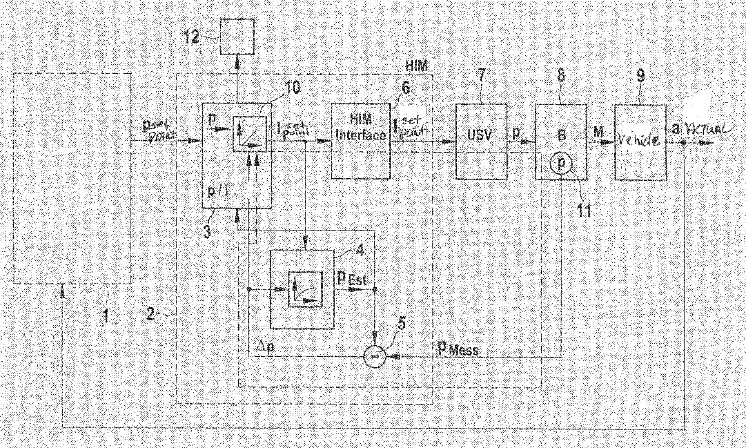
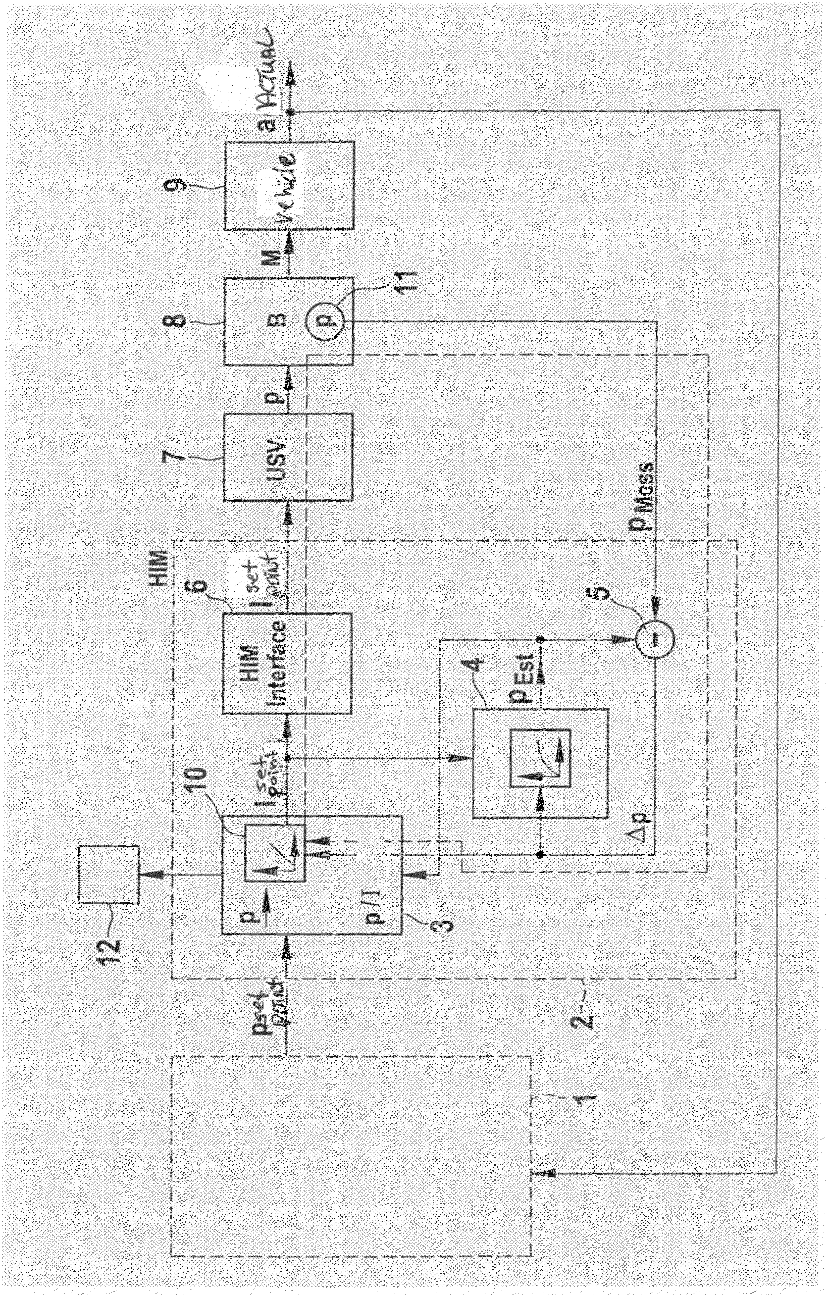
[0016]The FIGURE shows a schematic representation of the controller structure of a control loop for controlling brake pressure p in a hydraulic brake system. The layout includes a vehicle system 1 such as ACC, for example, which, by an automatic brake actuation, is able to intervene in regulating or controlling fashion in the vehicle operation. When vehicle system 1 becomes active, it generates a setpoint pressure value psetpoint, which is output to a pressure actuator 2. Vehicle system 1 and pressure actuator 2 are realized here as software modules which may be stored in one or in different control units.

[0017]Pressure actuator 2 includes a controller 3 having a valve characteristic curve 10 (p / I characteristic curve), which converts setpoint pressure psetpoint into a corresponding valve current Isetpoint. Valve current Isetpoint forms the controlled variable for a pressure-limiting valve 7 which is used to limit the brake pressure to a predefined threshold value. The level of brak...


PUM


Abstract

A device for controlling the brake pressure in a hydraulic brake system with the aid of a pressure-limiting valve that limits the brake pressure to a predefined threshold value, and to that end is driven by an electronic device in accordance with a valve characteristic curve. The setting accuracy can be improved considerably if an estimating unit for estimating the brake pressure, a sensor system for measuring the brake pressure, a unit for determining a pressure difference between the measured brake pressure and the estimated brake pressure, as well as a controller unit which drives the pressure-limiting valve as a function of the pressure difference are provided.

Description

FIELD OF THE INVENTION[0001]The present invention relates to a device for controlling the brake pressure in a brake system, particularly a hydraulic brake system, as well as a corresponding method.BACKGROUND INFORMATION[0002]Modern vehicles usually include various driver assistance systems which, in certain driving situations, automatically intervene in the vehicle operation in order to stabilize the vehicle or to otherwise assist the driver. Among these are, in particular, vehicle dynamics control systems such as ESP (electronic stability program), but also “driver-assistance systems” such as ACC (adaptive cruise control), as well as extra-value functions like, for example, APB (automatic parking brake) or a hill-hold function (HHC). These systems usually drive a hydraulic pump which builds up a desired setpoint brake pressure at a wheel. As a rule, the hydraulic pump is actuated in time-controlled manner. The driving time is defined by a model stored in the software.[0003]Because ...

Claims


Application Information

Patent Timeline
Patent Type & Authority Applications(United States)
IPC IPC(8): B60T8/36G06F17/00
CPCB60T8/36B60T8/365B60T2270/88B60T11/12B60T2250/00B60T8/4872
Inventor CREPIN, BETTINABUNK, MICHAELGALBAS, ROLANDKINDER, RALFSCHANZENBACH, MATTHIASBETZ, CHRISTOPH
Owner ROBERT BOSCH GMBH
Why Eureka
Try Eureka