Processing apparatus using source gas and reactive gas

a technology of processing equipment and source gas, applied in the direction of coating, chemical vapor deposition coating, metallic material coating process, etc., can solve the problems of inability to adopt, space-consuming trap device, higher cost, etc., and achieve the effect of solving the problem

Inactive Publication Date: 2009-08-27
TOKYO ELECTRON LTD
View PDF5 Cites 33 Cited by
  • Summary
  • Abstract
  • Description
  • Claims
  • Application Information

AI Technical Summary

Benefits of technology

[0015]In view of the foregoing context, the present invention has been made to effectively solve the problems. An object of the present invention is to provide a processing apparatus that does not allow a source gas and a reactive gas to simultaneously flow into a vacuum evacuating system, so that generation of unwanted deposits which may cause a malfunction of a vacuum pump can be prevented.
[0016]Another object of the present invention is to provide a processing apparatus that can restrain a maintenance frequency of a trap device for removing an impurity gas from an evacuated gas.
[0025]a reactive gas escape prevention valve disposed in the reactive gas by-pass line, that prevents an escape of the reactive gas from the by-pass line into the vacuum evacuating system when the valve is in a closed condition.
[0026]According to the processing apparatus, a source gas and a reactive gas are not allowed to simultaneously flow into the vacuum pump of the vacuum evacuating system through the respective by-pass lines. Thus, it is possible to prevent in the vacuum evacuating system generation of deposits which may cause a malfunction of the vacuum pump. For the same reason, a trap device is no longer needed, which was needed in a conventional vacuum evacuating system.
[0038]It is preferable that the vacuum evacuating system is provided with a scrubber that eliminates an impurity gas in an evacuated gas. In this case, since a source gas and a reactive gas are not allowed to simultaneously flow into the vacuum evacuating system, a combustion decomposition efficiency of an impurity gas such as SiH4 in a scrubber is improved, which increases detoxifying efficiency.
[0047]According to the processing apparatus, it is possible to evacuate the source gas through the unnecessary source gas evacuating system, for example, when causing the source gas to flow for stabilizing the flow rate. Thus, load of the (first) trap device is reduced in the vacuum evacuating system. As a result, it is possible to restrain a maintenance frequency of the trap device

Problems solved by technology

However, since this solution makes a process period so long as to deteriorate a throughput, it cannot be adopted.
However, the trap device is space-consuming.
In addition, since the trap device must be periodically exchanged to a new one, a maintenance operation is troublesome and requires a higher cost, resulting in deterioration in a throughput.

Method used


Image

  • Processing apparatus using source gas and reactive gas
  • Processing apparatus using source gas and reactive gas
  • Processing apparatus using source gas and reactive gas

Examples


first embodiment

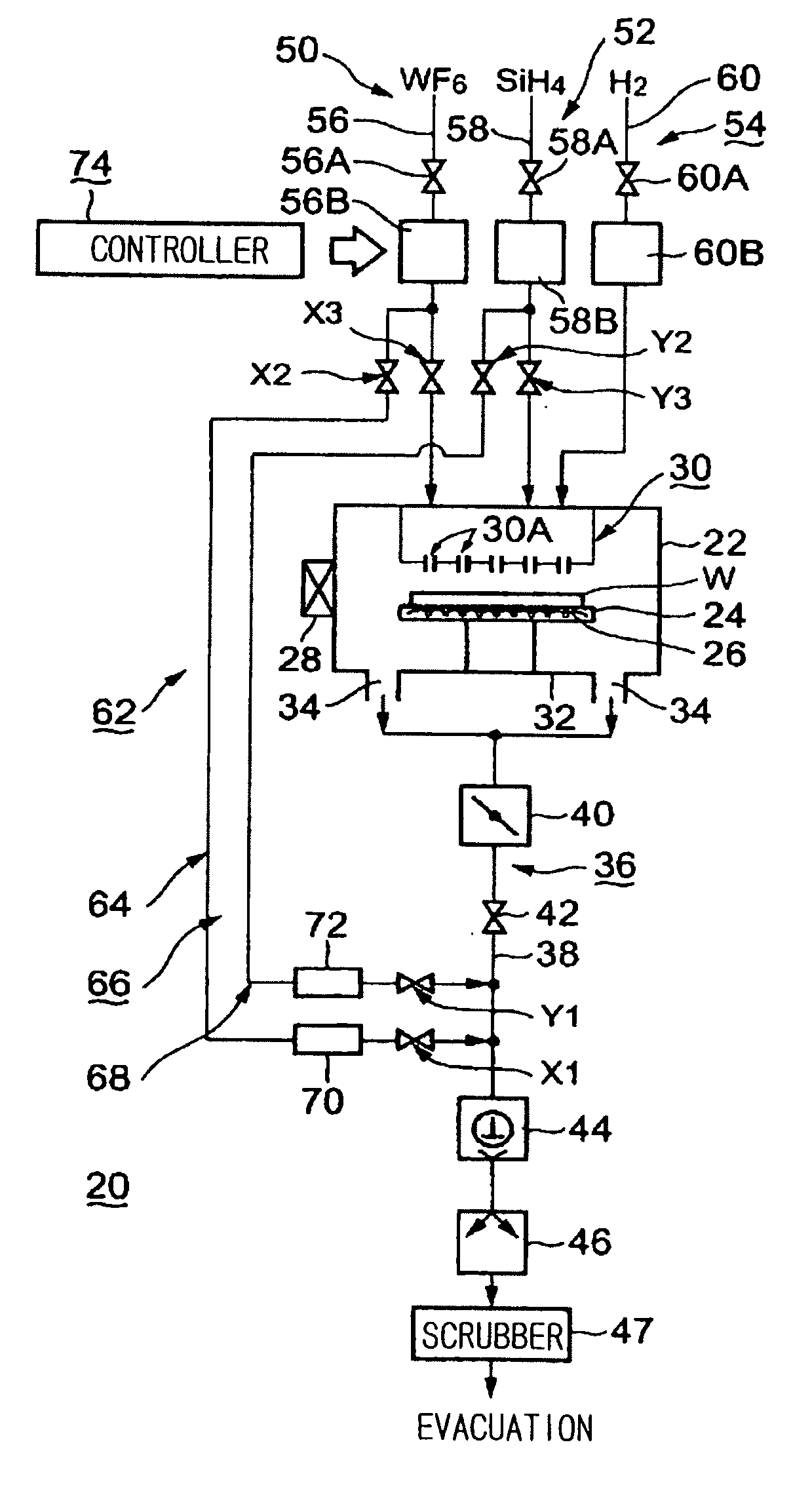
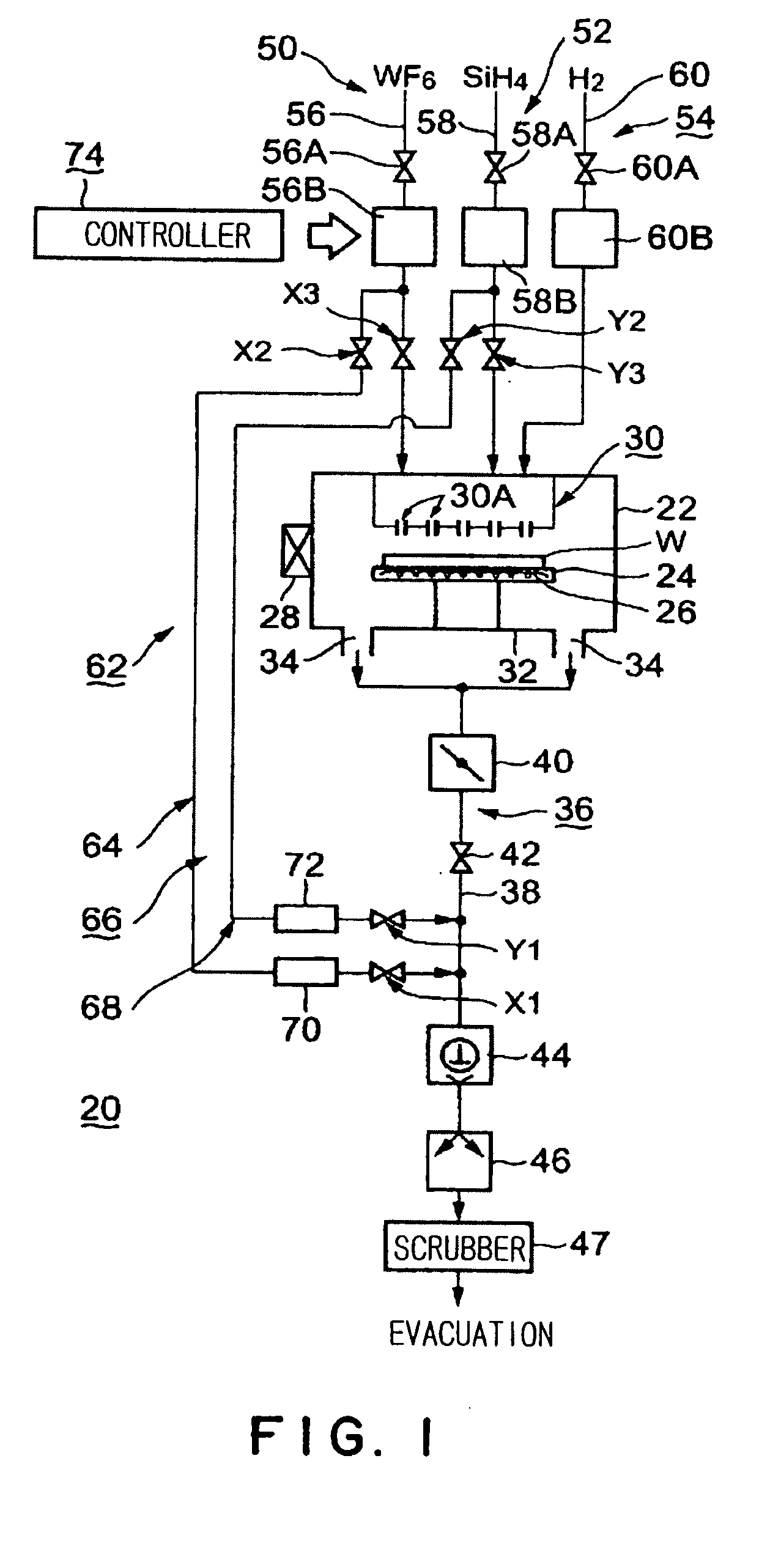
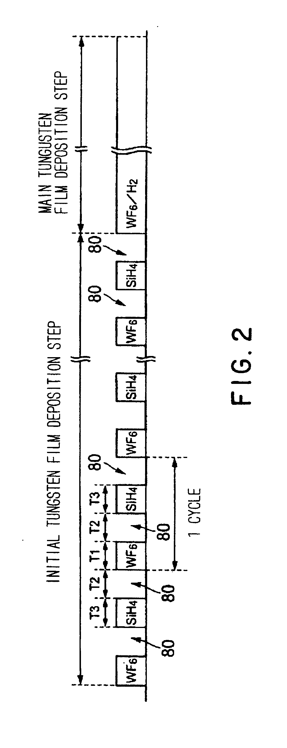
[0064]A first embodiment of the present invention shown in FIGS. 1 to 3 are described at first. In the first embodiment, a process in which a tungsten film (seeding film) is formed by supplying alternately, intermittently WF6 gas as a source gas and SiH4 gas of a reducing gas as a reactive gas, is described as an example.

[0065]As shown in FIG. 1, a processing apparatus 20 includes a cylindrical processing vessel 22 an inside of which can be evacuated to form a vacuum. A table 24 is disposed in the processing vessel 22. An object to be processed, such as a semiconductor wafer W, can be supported on an upper surface of the table 24. A resistance heater 26 as heating means is buried in the table 24, so that the wafer W can be heated to a predetermined temperature and maintained thereat. In place of the resistance heater, a heating lamp may be used as the heating means.

[0066]A gate valve 28 is disposed on a sidewall of the processing vessel 22, which is opened and closed when the wafer ...

second embodiment

[0113]A second embodiment of the present invention shown in FIGS. 6 and 7 is described, with also reference to a conventional example shown in FIG. 10. An object of the second embodiment is to restrain a maintenance frequency of a trap device disposed on a vacuum evacuating system. In the second embodiment, a TiN film is deposited by using TiCl4 gas and NH3 gas by a thermal CVD method.

[0114]A constitution of a processing vessel 22 of a conventional processing apparatus shown in FIG. 10 is the same as that of the processing vessel 22 shown in FIG. 1. Thus, the same parts are shown by the same reference numbers, and their description is omitted. A source gas supply system 90 for supplying, for example, TiCl4 gas as a source gas is connected to a showerhead part 30 disposed in the processing vessel 22. A flow rate controller 92A for controlling a flow rate like a mass flow controller is disposed on the source gas supply system 90. A valve 94 is disposed upstream the flow rate controlle...


PUM

PropertyMeasurementUnit
temperatureaaaaaaaaaa
pressureaaaaaaaaaa

Abstract

The present invention relates to a processing apparatus for performing a film-deposition process or the like for an object to be processed (such as a semiconductor wafer) by means of a source gas and a reactive gas. The processing apparatus includes: a processing vessel (22) that contains therein an object to be processed (W); a source gas supply system (50) that selectively supplies a source gas into the processing vessel; a reactive gas supply system (52) that selectively supplies a reactive gas into the processing vessel; and a vacuum evacuating system (36) having vacuum pumps (44, 46), the system exhausting an atmosphere in the processing vessel to form a vacuum. The processing apparatus further includes: a source gas by-pass line (62) that selectively feeds the source gas into the vacuum evacuating system with the source gas bypassing the processing vessel; and a reactive gas by-pass line that selectively feeds the reactive gas to the vacuum evacuating system with the reactive gas bypassing the processing vessel. The source gas by-pass line (62) has a source gas escape prevention valve (X1) that prevents an escape of the source gas from the by-pass line into the vacuum evacuating system when the valve is in the closed condition. The reactive gas by-pass line (66) has a reactive gas escape prevention valve (Y1) that prevents an escape of the reactive gas from the by-pass line into the vacuum evacuating system when the valve is in the closed condition.

Description

BACKGROUND OF THE INVENTION[0001]1. Field of the Invention[0002]The present invention relates to a processing apparatus that performs a film-deposition process for, e.g., a semiconductor wafer, by using a source gas and a reactive gas (such as a reducing gas and an oxidizing gas).[0003]2. Background Art[0004]In a manufacturing process of a semiconductor integrated circuit, an object to be processed such as a semiconductor wafer is generally, repeatedly subjected to various kinds of single-wafer processes, such as a film-deposition process, etching process, heat process, modification process, and crystallization process, so as to form a desired integrated circuit. In each of the various kinds of processes, a processing gas necessary for a certain process is introduced to a processing vessel. That is, a film-deposition gas is introduced to a processing vessel when a film-deposition process is performed. Similarly, an ozone gas is introduced for performing a modification processing, an...

Claims


Application Information

Patent Timeline
Patent Type & Authority Applications(United States)
IPC IPC(8): C23C16/54C23C16/455C23C16/44H01L21/285
CPCC23C16/4412H01L21/28562H01L21/28556C23C16/45561C23C16/52C23C16/455C23C16/4401C23C16/14
Inventor TANAKA, MASAYUKIKAI, KOUZOMURAKAMI, SEISHIMIYASHITA, TETSUYA
Owner TOKYO ELECTRON LTD
Why Eureka
Try Eureka