Rear contact solar cell and method for making same

Inactive Publication Date: 2009-08-27
INST FUR SOLARENERGIEFORSCHUNG
View PDF5 Cites 43 Cited by
  • Summary
  • Abstract
  • Description
  • Claims
  • Application Information

AI Technical Summary

Benefits of technology

[0013]It is an object of the present invention to avoid or at least minimise the above-mentioned problems, and to p

Problems solved by technology

However, conventional so-called rear contact solar cells are associated with several disadvantages.
In most cases their production processes are expensive.
Moreover, conventional rear contact solar cells are often plagued by local short-circuits, e.g. as a result of inversion layers between the base region and the emitter region, or as a result of inadequate electrical insulation between the emitter contact and the base contact, which leads to reduced efficiency of the solar cell.
The above is associated with a disadvantage in that these methods require several adjusting masking steps and are therefore expen

Method used


Image

  • Rear contact solar cell and method for making same
  • Rear contact solar cell and method for making same
  • Rear contact solar cell and method for making same

Examples


first embodiment

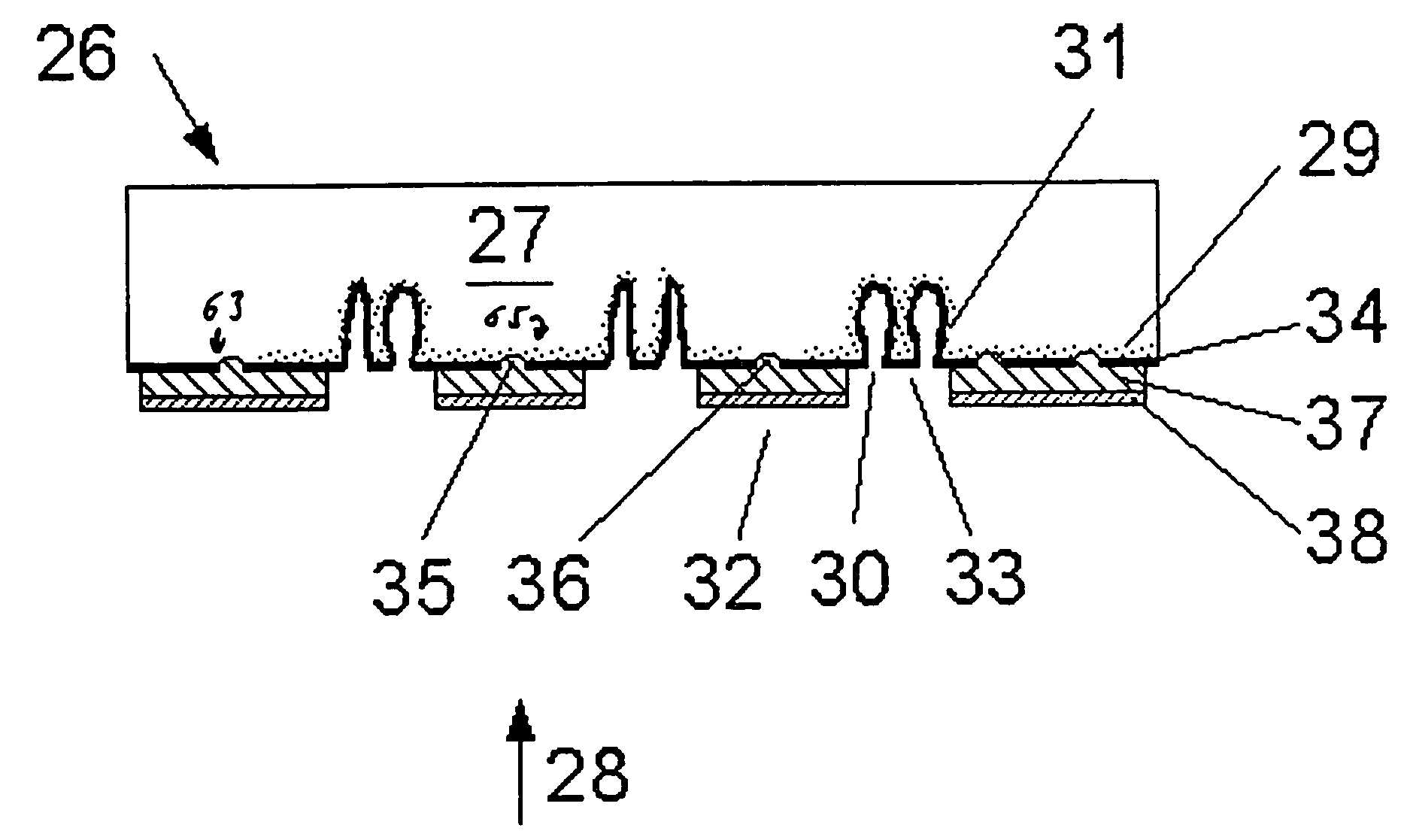
[0041]FIG. 2 diagrammatically shows a section view of a solar cell according to the invention according to a

second embodiment

[0042]FIG. 3 diagrammatically shows a section view of a solar cell according to the invention according to a

third embodiment

[0043]FIG. 4 diagrammatically shows a section view of a solar cell according to the invention according to a

DESCRIPTION OF PREFERRED EXEMPLARY EMBODIMENTS

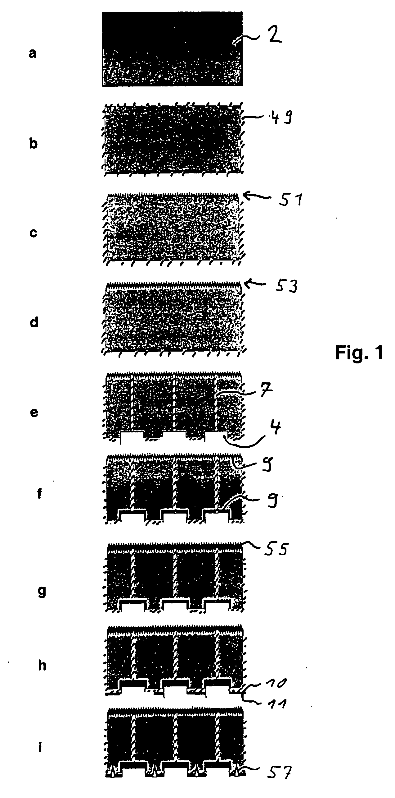
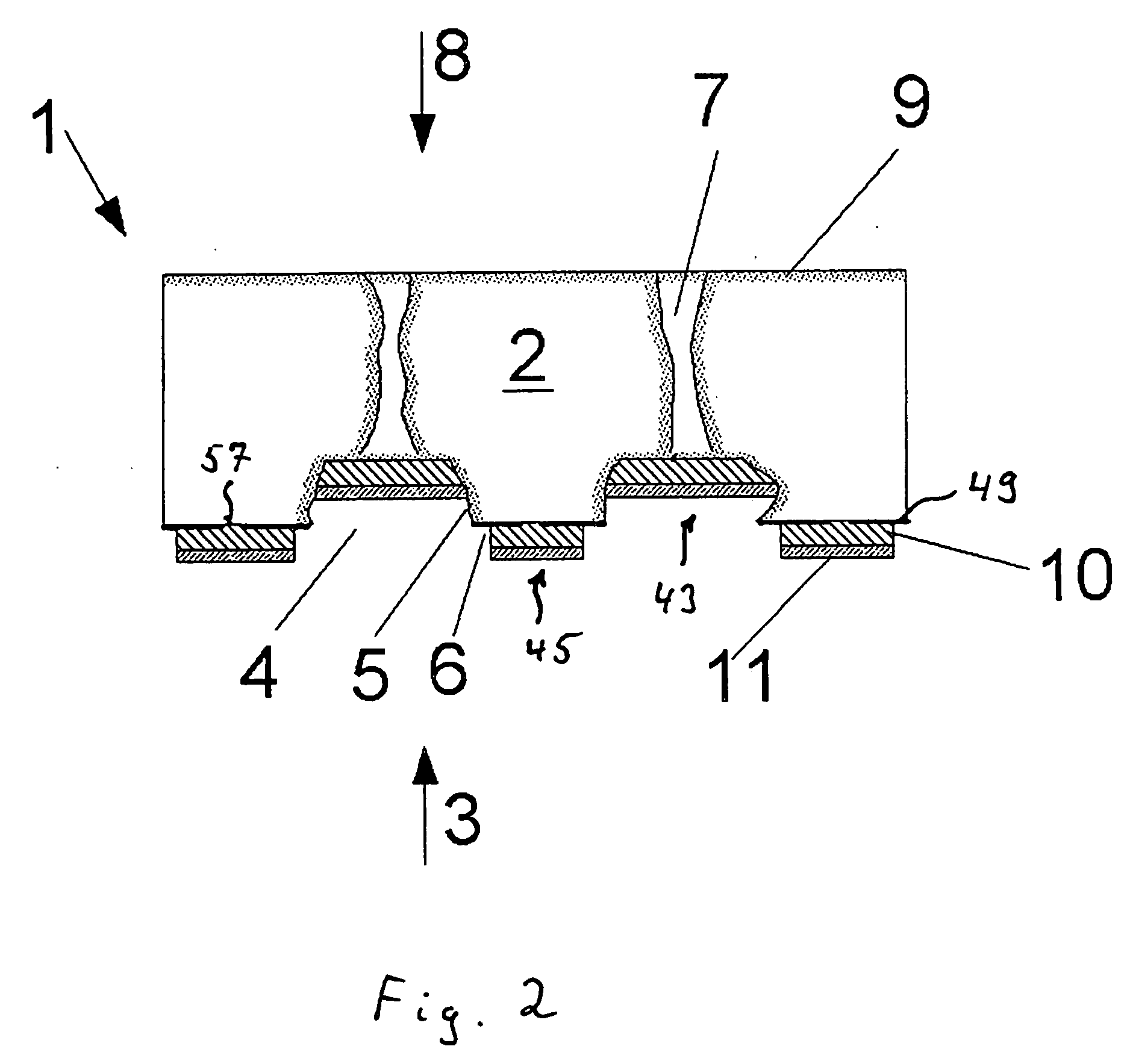
[0044]With reference to FIG. 1, first an embodiment of a production method according to the invention is described, as can be applied in a similar way in the production of the solar cell 1 according to the invention, which solar cell is shown in FIG. 2.

[0045]First (in step a) a silicon wafer 2 is subjected to tenside cleaning in a heated ultrasonic bath. Subsequently, the damage caused during sawing of the wafer is edged off in heated KOH, wherein approximately the outermost 10 μm of the wafer is removed. Subsequently, the wafer is subjected to so-called RCA cleaning, wherein the wafer surface is oxidised by a sequence of NH4OH-, HF-, HCl- and HF-rinses, with the oxide subsequently being etched off.

[0046]Next (in step b) the entire wafer surface is oxidised in an N2 / O2 atmosphere at approximately 1050° C. to an oxide thickness of a...


PUM


Abstract

The invention concerns a solar cell (1) and a method for making same, said solar cell (1) comprising on its rear surface (3) both the emission contact (43) and the base contact (45), those two contacts (43, 45) being electrically isolated from each other by flanks (5) whereof the metal coating has been removed. The emitting zones (4) of the rear surface (3) of the cell are connected by channels to the transmitter (9) of the front face (8) of the cell. The emitting zones (4) of the rear surface (3) of the cell and the channels (7) consist of a laser. The metal coating of the side walls is removed by selective etching, said metal coating being removed only in the zone of the flanks (5) where the etching barrier layer (11) is insufficient.

Description

FIELD OF THE INVENTION[0001]The present invention relates to a solar cell, in which both an emitter contact and a base contact are arranged on a rear surface of a semiconductor substrate, and to a method for making said solar cell.BACKGROUND TO THE INVENTION[0002]Solar cells are used to convert light into electrical energy. In this process, in a semiconductor substrate, charge carrier pairs that have been generated by light are separated by means of a pn-junction, whereupon they are fed, by way of the emitter contact and the base contact, to an electrical circuit comprising a consumer.PRIOR ART[0003]In conventional solar cells the emitter contact is usually arranged on the front, i.e. on the face pointing towards the light source, of the semiconductor substrate. However, e.g. in JP 5-75149 A, DE 41 43 083 and DE 101 42 481, solar cells have been proposed in which both the base contact and the emitter contact are arranged on the substrate rear. On the one hand in this arrangement sha...

Claims


Application Information

Patent Timeline
IPC IPC(8): H01L31/0224H01L21/28
CPCH01L31/022458Y02E10/547H01L31/1804Y02P70/50
Inventor ENGELHART, PETERTEPPE, ANDREASGRISCHKE, RAINERWADE, ROBERT
Owner INST FUR SOLARENERGIEFORSCHUNG
Why Eureka
Try Eureka