Pulse circuit using a transmission line
- Summary
- Abstract
- Description
- Claims
- Application Information
AI Technical Summary
Problems solved by technology
Method used
Image
Examples
Embodiment Construction
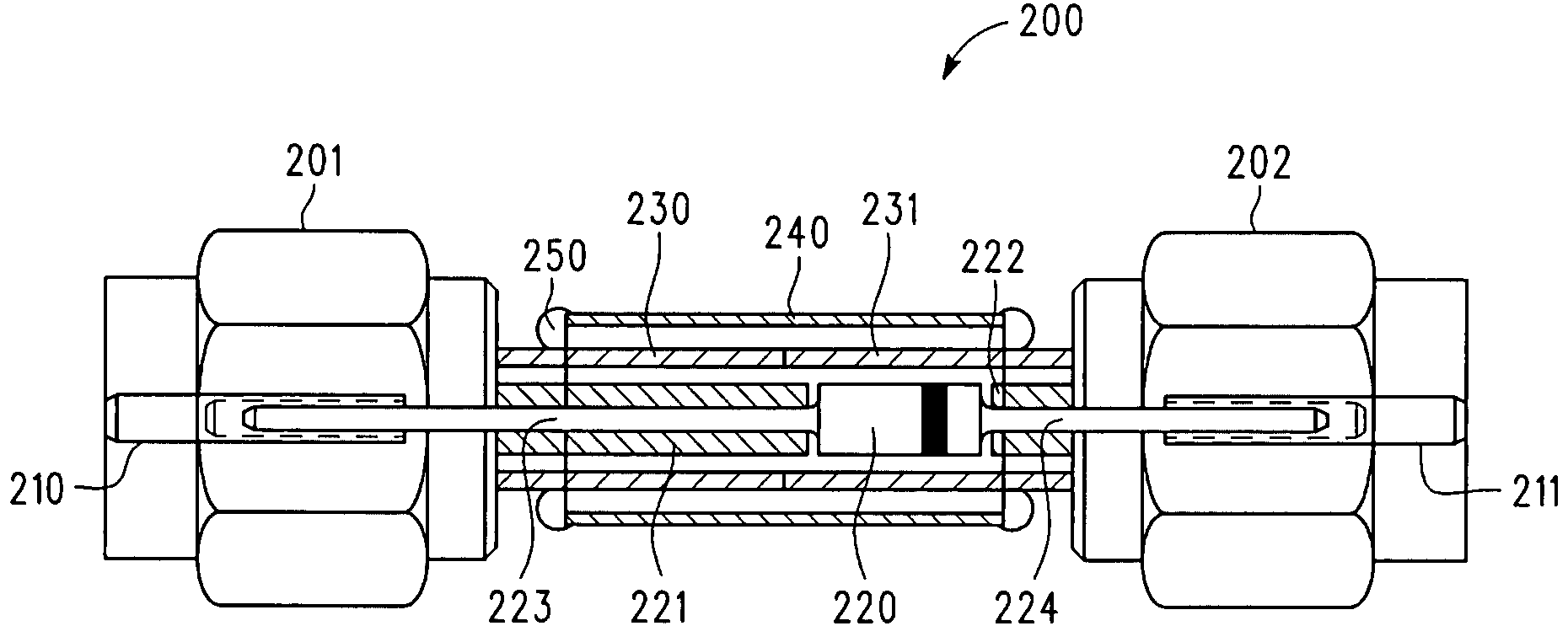
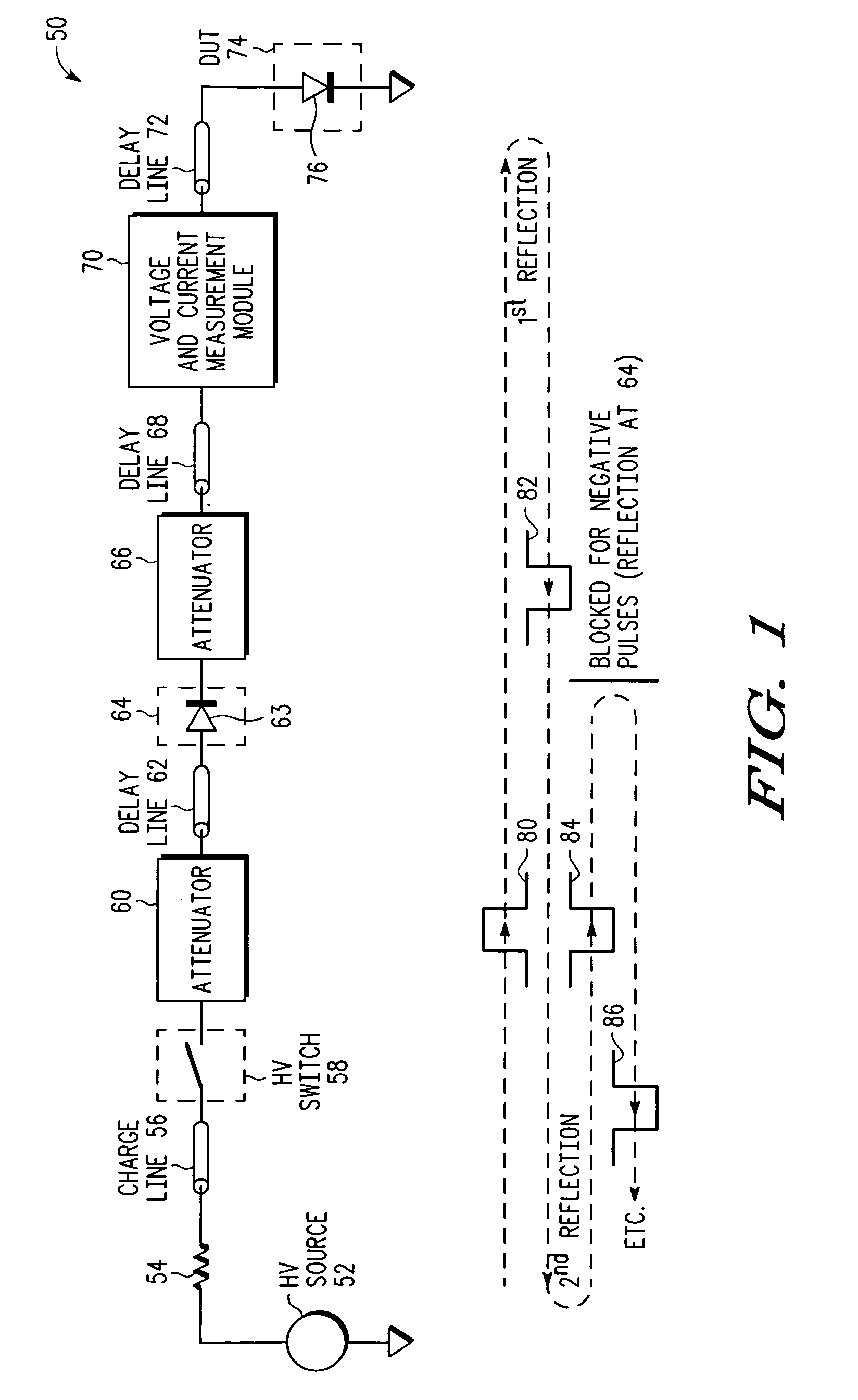
[0008]Referring to FIG. 1, pulse 80 represents a pulse produced by high voltage source 52, resistive element 54, charge line 56, and high voltage switch 58. In the illustrated embodiment, pulse 80 has positive voltage polarity and is transmitted to DUT 74 via attenuator 60, delay line 62, selective pulse blocking module 64, attenuator 66, delay line 68, voltage and current measurement module 70, and delay line 72. In this embodiment, the selective pulse blocking module 64 acts like a “through connection” for pulses with positive polarity (e.g. pulse 80) traveling from the charge line 56 towards the DUT 74. For pulse 80, which has positive voltage polarity, the DUT 74 exhibits a resistance that is lower than the system impedance (e.g. approximately 50 Ohms for one embodiment of test system 50) and therefore causes a reflected pulse 82 (first reflection) having opposite (i.e. negative) voltage polarity with respect to pulse 80. This first reflection is comparable to a reflection at a ...
PUM
 Abstract
Description
Claims
Application Information
 - R&D Engineer
- R&D Manager
- IP Professional
- Industry Leading Data Capabilities
- Powerful AI technology
- Patent DNA Extraction
Browse by: Latest US Patents, China's latest patents, Technical Efficacy Thesaurus, Application Domain, Technology Topic, Popular Technical Reports.
© 2024 PatSnap. All rights reserved.Legal|Privacy policy|Modern Slavery Act Transparency Statement|Sitemap|About US| Contact US: help@patsnap.com


